"Pedly" 3-D Seismic Program
Historical background
Late 1970's 2-D exploration in northern Canada revealed a pinnacle reef structure, in the "Leduc" formation. The structure appeared to be promising, but Mobil Oil of Canada, who owned the exploration rights, was uncertain of the commercial value of the property. By 1996 favorable market conditions, coupled with decreasing costs for 3-D seismic acquisition and processing, made a cost effective exploration program over the target formation an economically feasible project.
Program Objectives
The common goal of most commercial seismic exploration programs is to provide interpretable data in the most cost effective manner possible. The Pedly program was no exception, Mobil designed the 3-D seismic survey to explore the formation and determine the following:
- Exact size and location of the reef structure.
- Commercial viability of the structure.
- Most favorable drilling locations for exploitation of the structure.
Design Criteria
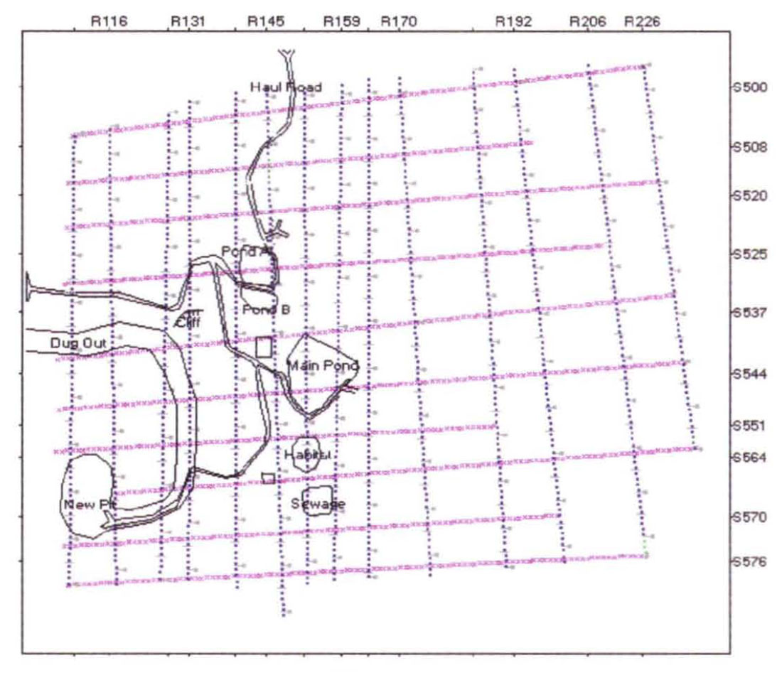
Mobil's project design made use of existing "cut-lines" and "clear-cut" areas wherever possible. The project was in a heavily forested, mountainous region where efforts were made to minimize environmental impact and, therefore acquisition costs. The nature of the target allowed for 30-meter bin sizing using 60-meter station intervals, while source and receiver line spacing varied from 200 to 600-meters, as surface conditions dictated. The other factor, which had to be accounted for was that a large scale open-pit (or "strip") coal mining operation was situated almost directly over the target structure. This, obviously, introduced a massive amount of surface culture, which had to be planned around. Source and receiver lines where moved to accommodate mining operations, processing facilities, settling ponds, and ore-hauling roads. It became obvious in the planning stages that a traditional approach to cable telemetry recording would not be possible. Figure 1. Shows a project pre-plan including the surface culture introduced by the mine.
It should be noted that although the Pedly acquisition program presents itself as a good candidate for the use of radio telemetry acquisition, this option was not available due to restrictions on radio use within the mine area. This case study, shows that in many cases where radio telemetry appears to be the logical choice due to cultural difficulties, a cable based system using network telemetry methods may in fact be preferable.
Traditional Cable Telemetry
Basic Functions
Major advances have taken place in systems design in the last few years with respect to digitization accuracy, channel and geophone testing, and overall system capacities. Telemetric function, however, has remained virtually the same for over two decades.
Telemetric digitizing units are deployed in continuous lines, interconnected by receiver cables. Telemetric "Crossing Units" are deployed at intersections between the receiver cables and the "base-line" or telemetry " trunk-line" returning the telemetry data to the Central Recording Unit. The "base line" is served by specialized cables, designed to carry the increased telemetry traffic between CRU and receiver lines. It is a simple and effective arrangement, which has worked as stated, for over two decades.
Limitations
The drawback to this simplicity is that it necessitates a deployment that follows this pre-defined, geometrically orthogonal pattern. Figure 2. Shows a typical equipment deployment for a traditional telemetry system, overlaid on the Pedly 3-D project. The logistical problems encountered are the many cable crossings on graded ore-hauling roads, the necessity to deploy equipment in both the active mining area and the settling ponds, and the large amount of non-digitizing telemetric equipment (or telemetry "repeaters"), required to detour receiver lines around these obstructions.
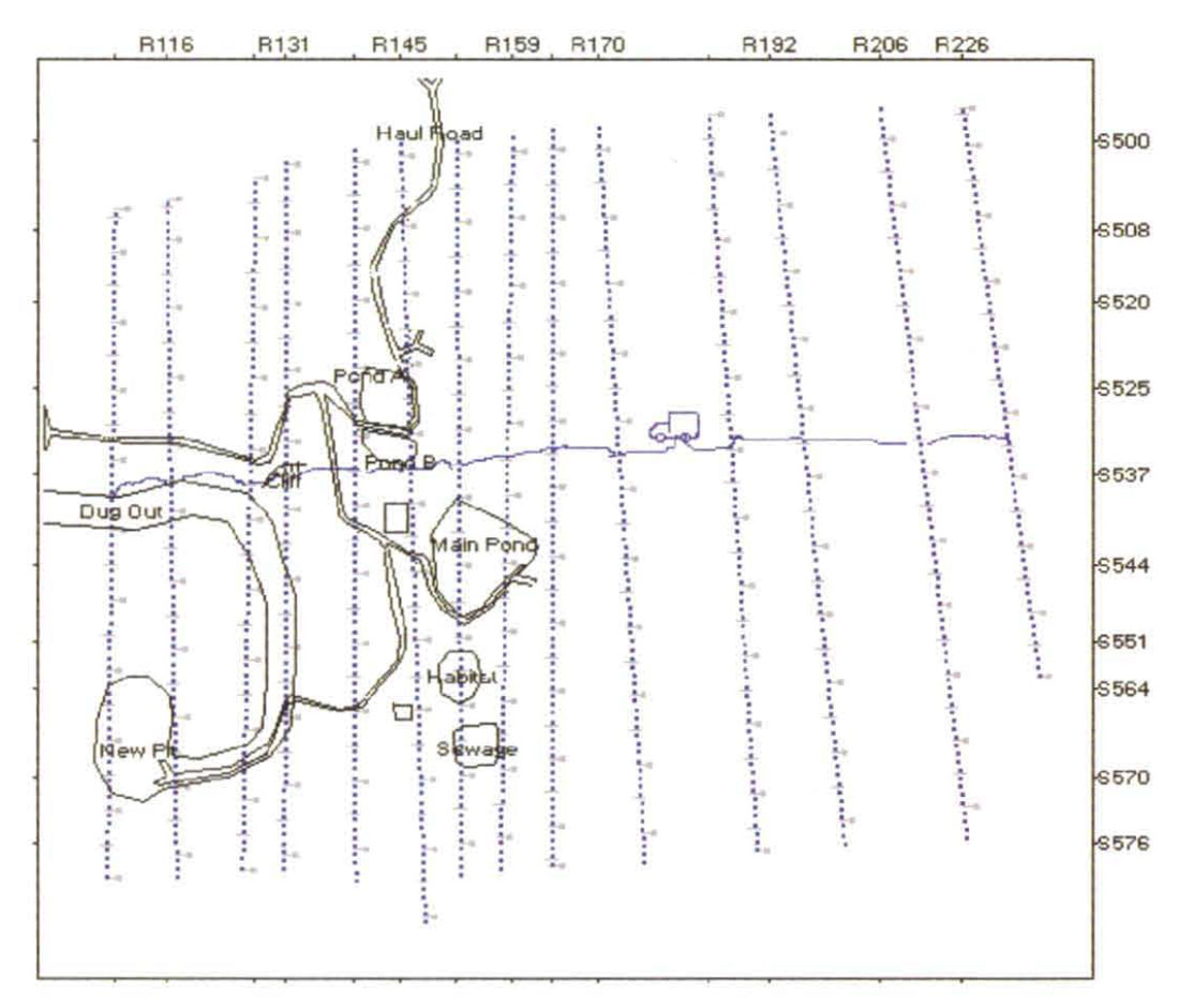
The most difficult of these problems logistically with would be the cable crossings on the ore-hauling roads. The equipment traveling these roads was of such a size and nature as to guarantee the destruction of each telemetry cable crossed. A team would have to be deployed at each of the many crossings, in order to retrieve the telemetry cables as the mining equipment approached, and redeploy it after the equipment passed. This option did not seem practical, as the mining equipment was moving up and down these haul roads on a regular basis, twenty-four hours per day. These logistical problems may have either forced the restriction of the acquisition program, or it's cancellation altogether.
"Network" Cable Telemetry
Basic Functions
The key differences provided by network telemetry are primarily functions that were borrowed from the communications, and computer networking industries. Instead of treating the individual digitizing telemetry units as parts of a receiver line, they are treated as addressable "nodes" in what is effectively, a communications network.
Traditional cable telemetry depends on the rigidly ordered telemetry" connections themselves to determine the deployment geometry. Network telemetry separates the telemetric function of each "node" from it geometric location. In other words, its location on the ground is determined regardless of how its telemetry reaches the CRU. This allows absolute freedom during deployment. Digitizing units need not be connected in a trace sequential fashion as a prerequisite for geometrically correct sequencing of the data. One of the Simplest examples of the network concept is when nodes on adjacent receiver lines are cabled together in a snaking manner. Effectively, this results in a telemetry stream where adjacent digitizing units are on completely separate receiver lines, a condition that baffles the " traditional" cable telemetry systems.
Where traditional cable telemetry systems use "crossing station units", network telemetry intersections are handled by telemetric "hubs" which can be located anywhere on the telemetry spread. Their function is not merely to direct receiver line traffic towards the CRU, it is to facilitate communication between groups of "nodes" on separate cables. Again, the flexibility of this methodology allows more freedom during deployment. As functional network hubs, the "Line Tap Units" can be connected to receiver lines in the traditional manner. More importantly they may be connected "through" receiver lines, using the receiver line and its digitizing nodes as telemetry carriers to extend base line service to other parts of the network.
The final component necessary for network telemetry is the ability to connect multiple base lines to the CRU. The CRU used to record the Pedly project was configured with eight base line interfaces, and six were used.
These descriptions may give you a brief understanding of the operational advantage of network telemetry, but to truly understand the operational benefits available we must study an example of the system in use.
"Pedly" Deployment Example
The Pedly 3-D program is an excellent example of utilizing "network" telemetry to avoid, or ameliorate, some of the most difficult acquisition problems a contractor may, from time to time, be faced with.
The most challenging problem posed by the project were the large number of places where receiver cables had to cross mining roads that were effectively un-crossable. Utilizing network telemetry reduced cable crossings on mining roads from twelve to three, a number easily handled by employing microwave units.
Another major problem presented by this area was the large amount of equipment in hazardous areas, such as the active mine area and settling ponds. Since continuous receiver segments are not necessary when using network telemetry, no crossings in these areas were required. Figure 3. Shows the actual cable and telemetry equipment deployment used to record this challenging 3-D.

The diagram in Figure 3. shows multiple baselines in use, six different networks of telemetry equipment were connected independently to the Central Recording Unit. The ability to use multiple baselines is a tremendous advantage operationally, allowing separate groups of equipment to be deployed on either side of impassable obstructions. In this example, the impassable obstruction is the mining road, in other areas it may be a steep ravine or gorge, a fast moving waterway, or virtually any other lateral obstruction that may impede deployment.
The diagram also shows several receiver lines on the west end of the project, that are being retrieved via completely separate networks. Line R116 for example, is divided into four separate telemetry segments, routed to the CRU over three different line interfaces. This is simply not possible under the traditional cable telemetry system. It demonstrates the ability of network telemetry to retrieve geometrically sequential data from telemetrically disparate sources, by sorting the trace data according to the known geometry regardless of how the telemetry data physically reaches the CRU.
Figure 4. Shows the first "network" connected to the CRU. A microwave unit was deployed at the CRU to cross over the mine road. Network telemetry receiver lines and base lines are identical both in terms of physical cable characteristics and telemetry function, as a result, a single microwave unit can service either type of connection. The microwave can also be used to carry the entire telemetry bandwidth available through the cable so that, as in this example, an entire line interface is served via the microwave.
A telemetry base line was used to connect, through line tap units, the first few receiver line segments. Only the receiver line segments north of the mining road a reconnected on this network, avoiding any cable crossings on the road. This method also works very well for areas where busy highways intersect the receiver lines. By eliminating road crossings wherever possible, contractors can reduce damage to receiver line cables, and also avoid the dangerous necessity of having workers on the highway.
The deployment crew chose to snake the last two receiver lines together. They are free to do this whenever logistics dictate that it is more convenient for them. The network addresses the digitizing units independently, so it can retrieve data from any unit required for any particular source point. This allows the network telemetry "active spread" to roll through any combination of deployed units for any source point, whether they are cabled together through Line Taps or via "snaked" lines.
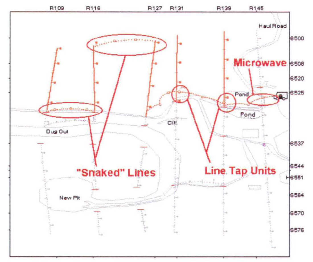
Figure 5. Shows the second network. This small network retrieves data from the area between the north mining road, and the south mining road and dugout area. The base line is run just south of the mine road and settling pond.
Receiver line R139, which is bisected three times by mining roads, is the first segment connected to the CRU. This first segment is only a few stations between the first and second branch of the mine road. Although it may not be clear from the diagram, this line is broken at the second branch of the road. The third segment of R139 will be connected through a snaked line to the adjacent receiver line.
The rest of the network is connected through a microwave unit, which crosses the lower fork of the mining road and a combination of line taps and snaked lines.
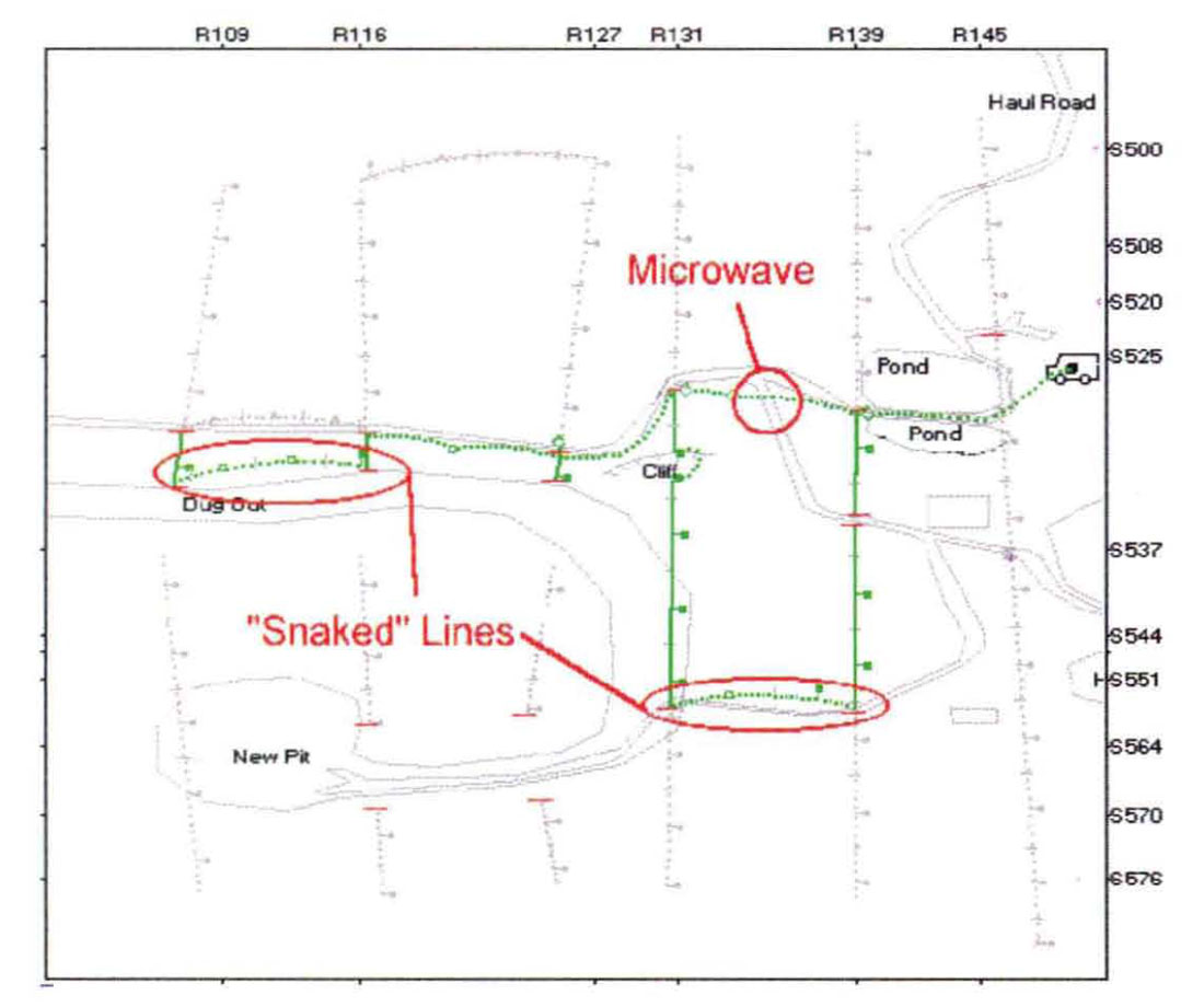
Figure 6. Shows the third network connected to the CRU. This is the most complex network on the project, and it utilizes nearly every advanced feature of network telemetry.
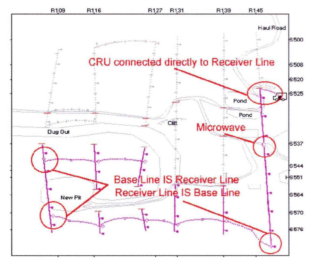
The first thing to note is that the CRU is connected directly to receiver line R145. This is only possible because base lines and receiver lines are telemetrically identical, and of itself this feature can represent a significant cost savings to the contractor. On traditional cable telemetry systems the CRU can only be connected to receiver lines through a "Crossing Station", obviously this is not necessary with network telemetry.
A microwave unit is employed midway down R145 to cross another section of mining road. This is the third and final microwave unit on the project and shows the power of network telemetry to eliminate unnecessary road crossings. In this example, the nature of the obstruction alone, coupled with the number of crossings, would have made this project impossible without the use of network telemetry. It should be remembered, that in areas where obstructions are merely difficult and not impassable, network telemetry can reduce deployment time by virtue of eliminating the difficult crossings.
The next thing which should be noted, is that the receiver line R145 is connected to a line tap. acting as a telemetry "hub", in order to extend a base line south of the mine roads towards the west end of the project. Receiver line segments are connected to this base line through line taps until it reaches the western-most line. Then the base line again is "carried" through the receiver line to the north, around the mining pit area. Safely past the pit, the receiver line is connected through another line tap to a short base line running east. This base line connects the last few receiver line segments isolated within the working mine area.
Conclusion
It should be apparent to both contractors and exploration geophysicists alike, that the flexibility of network telemetry can enhance any crew's ability to perform well in difficult regions. Whatever the obstacle: rugged topography, heavy forest, swamp, or man-made obstructions, network telemetry can give the operator the freedom to work around difficulties, instead of through them. Network telemetry can effectively give the crew the flexibility of a radio telemetry system, with the operational efficiency and relatively low cost of a cable telemetry system.


Join the Conversation
Interested in starting, or contributing to a conversation about an article or issue of the RECORDER? Join our CSEG LinkedIn Group.
Share This Article