Fiber-Optic Distributed Acoustic Sensing (DAS) applied to microseismic has the potential to significantly change the cost structure and quality of microseismic data acquisition. When a fiber-optic cable is deployed down-hole, it can be used for many purposes: hydraulic fracture monitoring, flow monitoring, VSPs and microseismic. Economies of scale are achieved when using a single fiber for all these purposes.
In the case of microseismic the use of DAS is rapidly becoming attractive. A conventional geophone microseismic acquisition involves deploying tools down-hole, moving them multiple times, and habitually also includes drilling a dedicated observation well. The fiber-optic cable however is non-intrusive, eliminating the need for well interventions and completions down time and perhaps a dedicated observation well. It requires a smaller footprint and fewer resources, reducing HSE exposure associated with well intervention to move (or deploy) geophones.
Although (at this time) DAS still lags behind geophones in terms of sensitivity, we have confirmed the hypothesis that the large aperture available to DAS allows more accurate positioning of events, thus enabling us to paint a far more accurate picture of the induced hydraulic fracture.
Locating DAS Microseismic Events and Errors
Shell has developed a fast data driven workflow for DAS microseismic that eliminates the need for hand picking events as is often done on geophone data, which can be a source of error. The method used to locate DAS microseismic events takes advantage of the large aperture. As a test, 7 stages of DAS microseismic events at a well were located in 2 days, which took a contractor 6 months to do on the geophone data.
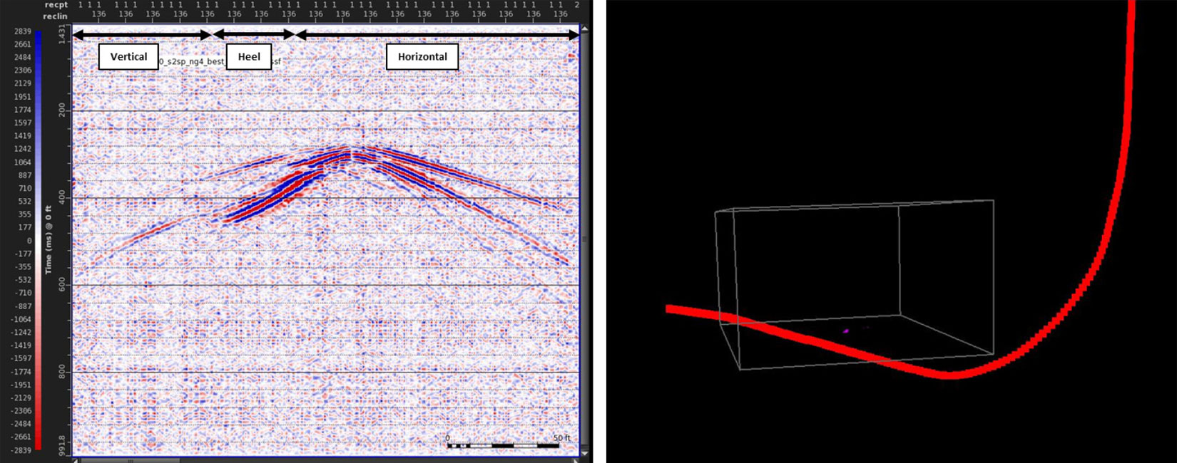
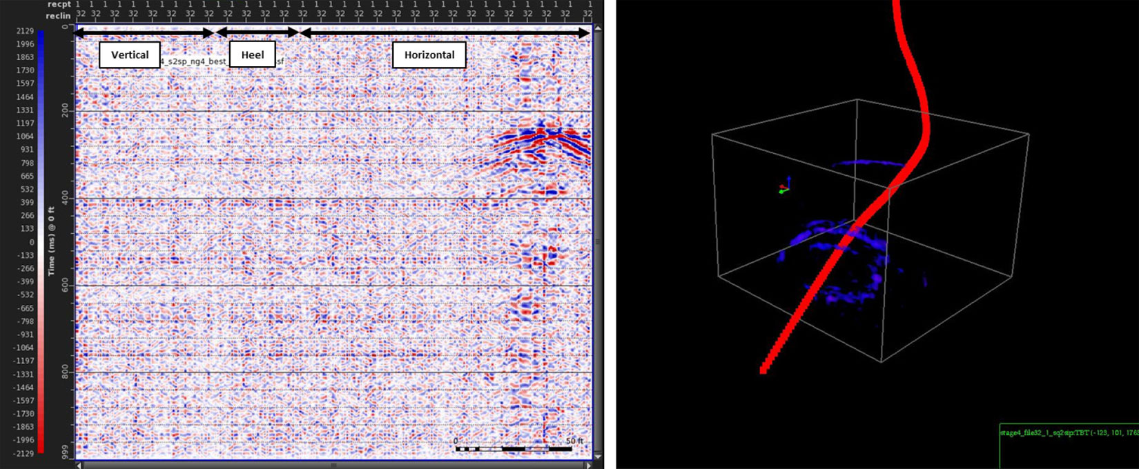
Geophones use three components (oriented at right angles) to determine the direction from which the event occurred. DAS only has the equivalent of a single component geophone. However, if the well is deviated, this effectively gives a second and third component (as the fiber itself is oriented differently along the well bore). This allows the direction of the event to be established. As a consequence we require the signal to be recorded around the heel of the well in order to locate a DAS microseismic event. In other words the heel of the well acts as a centre of the radius of investigation similar to the location of a vertical observation well.
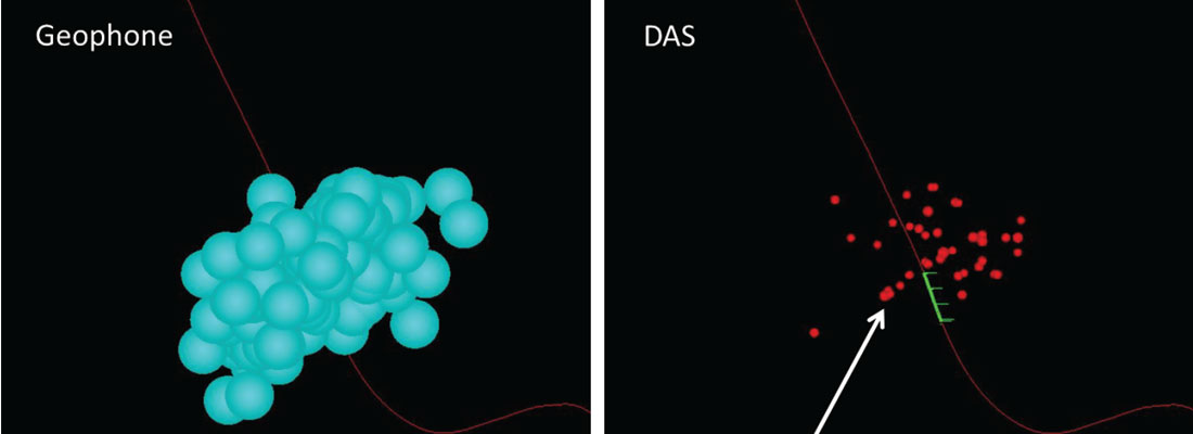
DAS and Geophones used to locate microseismic events
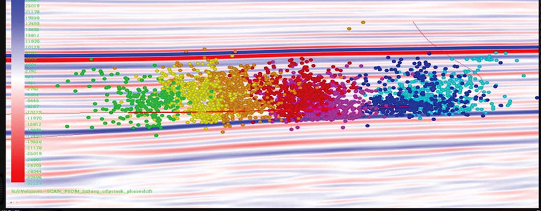
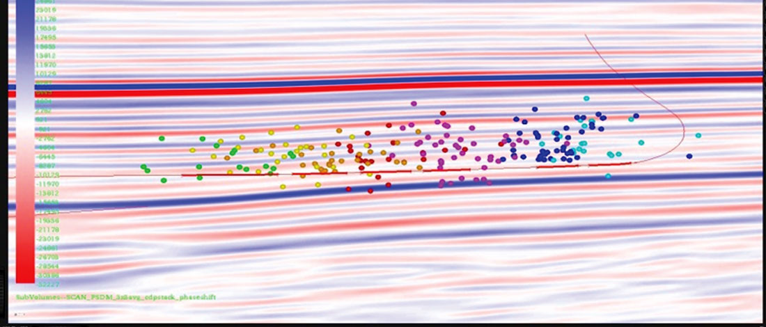
Using the above techniques we have located events from 7 stages of a well and compared to those located using a geophone array in the same well. Figure 4 shows microseismic events located by a contractor using geophone data, coloured by stage, on a horizontal well that was hydraulically fractured. Figure 5 shows the same well and stages with events detected and located with DAS. It can be seen that although fewer events are detected (about 10% of the events detected from geophone data) the DAS data shows a similar interpretation in terms of fracture height and width.
In practice, the error of events located by geophones are typically on the order of 30-50 m. Recognizing that the “accuracy” of geo-phone event detection has stayed the same, well spacing in unconventionals has become increasingly tighter from 400 m to 200 m or 100 m and typical fracture spacing currently being investigated can be as close as 50 to 20 m. The error associated with a microseismic event located using DAS can be determined by using the effective aperture (i.e. the channels that contributed to the location of the event). These errors are on the order of 1-2m.
Conclusions
We can now locate DAS microseismic events. Although fewer events are detected on DAS, the errors of those events are much smaller than those of geophones, potentially allowing a more confident interpretation of the fracture behavior. In addition DAS sensitivities are increasing and are expected to further increase in the next year, so that DAS may become a truly viable microseismic technology.
In addition, when the expense of deploying fiber in the field is offset by utilizing the other applications of DAS (fracture monitoring, flow monitoring, VSPs) we have a value proposition that as a combination can be more cost effective that traditional diagnostics deployed on a pad.

Acknowledgements
Shell Teams: Technology Excellence & Deployment team; Bill Westwood, Alan Reynolds. Asset team; Babak Akbarnejad. IT Support; Richard Tummers, Brad Hartmann. Data Management; Arlene O’Donnell. OptaSense: David Hill, Andrew Lewis, Jim Roy.


Join the Conversation
Interested in starting, or contributing to a conversation about an article or issue of the RECORDER? Join our CSEG LinkedIn Group.
Share This Article