Introduction
The present state of modern industrial development is characterized by the consumption of enormous quantities of petroleum. It is not used simply for the production of various fuels and lubricants; with each passing year more and more petroleum is used for manufacturing synthetic rubber, synthetic fibers, plastics, drugs, and thousands of other products. While demand for petroleum products continuous to rise, petroleum production worldwide is in a steady decline. However, new developments in technology and the rise in world oil prices give promise that substantial portions of otherwise neglected oil can be recovered. These new technical developments fall under the broad heading of enhanced oil recovery (EOR). Enhanced oil recovery is a collection of general methods, each with its own unique capability to extract the most oil from a particular reservoir. Each has been investigated rather thoroughly both from a theoretical and laboratory perspective, as well as in the field.
Over the years, interest in enhanced oil recovery (EOR) has been tempered by the increase in oil reserves and production. Many techniques have been investigated in the laboratory and the field for improving oil recovery. Historically the discovery of major oil fields in the world added large volumes of oil to the worldwide market. In addition, estimates of reserves from reservoirs in the Middle East increased significantly, leading to the expectation that the oil supply would be plentiful. Although large volumes of oil remain in mature reservoirs, the oil will not be produced in large quantities by EOR processes unless these processes can compete economically with the cost of oil production from conventional sources. Thus, as reservoirs age, a dichotomy exists between the desire to preserve producing wells for potential EOR processes and the lack of economic incentive because of the existence of large reserves of oil in the world. During the life of a well, oil recovery has three stages or categories which are:
- Primary Oil Recovery
- Secondary Oil Recovery
- Tertiary Oil Recovery
Enhanced Oil Recovery Techniques
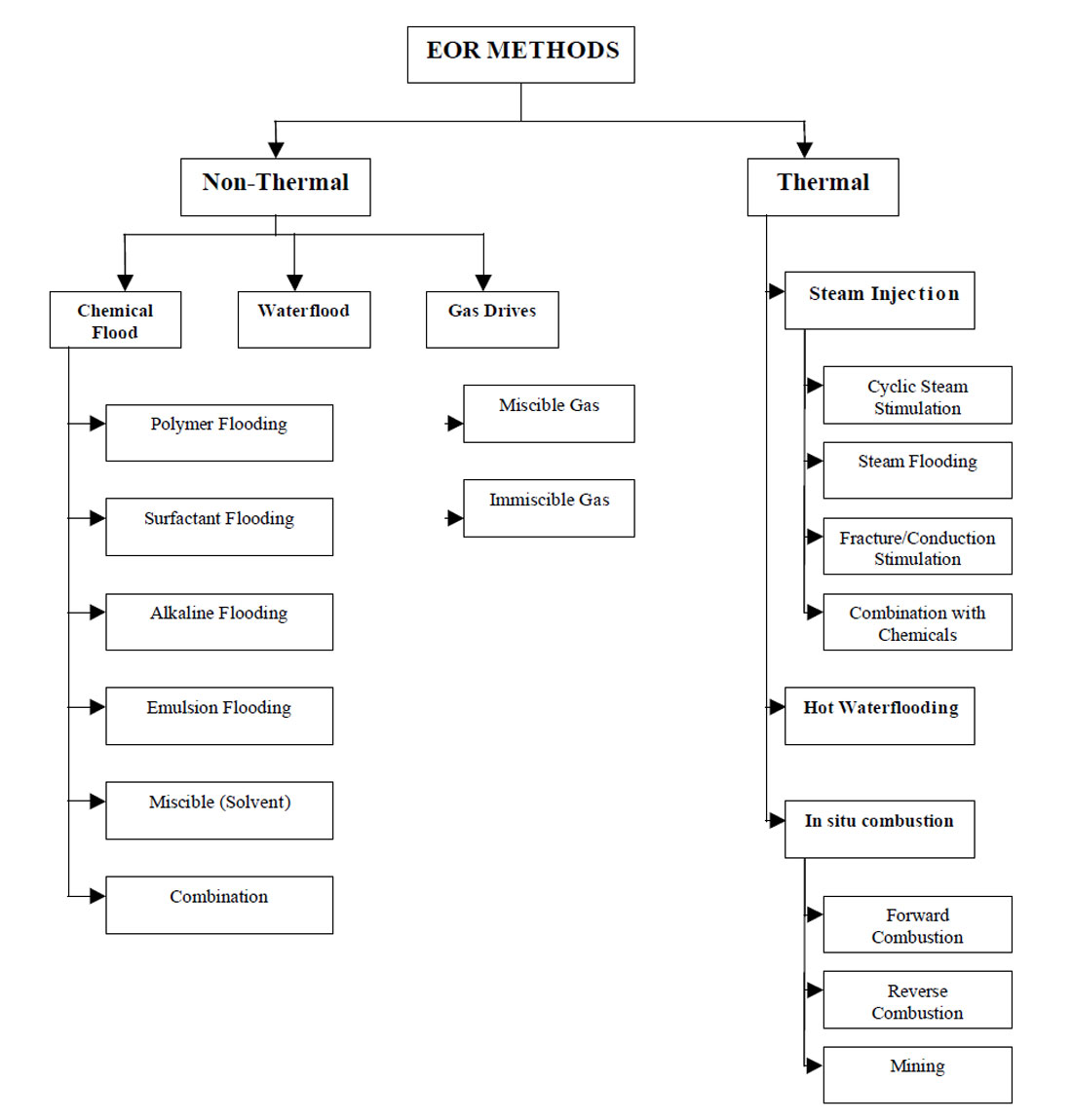
The term enhanced oil recovery (EOR) basically refers to the recovery of oil by any method beyond the primary stage of oil production. It is defined as the production of crude oil from reservoirs through processes taken to increase the primary reservoir drive. These processes may include pressure maintenance, injection of displacing fluids, or other methods such as thermal techniques. Therefore, by definition, EOR techniques include all methods that are used to increase cumulative oil produced (oil recovery) as much as possible. Enhanced oil recovery can be divided into two major types of techniques: thermal and non-thermal recovery.
Non-Thermal Recovery
Non-thermal recovery techniques can be broken down into the following:
Pressure Maintenance. More complete recovery of oil is achieved by special technological methods. A common method employed today is artificial maintenance of formation pressure. This traditional step for increasing oil recovery involves the injection of fluid into (or near) an oil reservoir for the purpose of delaying the pressure decline during oil production. Pressure maintenance can significantly increase the amount of economically recoverable oil over that to be expected with no pressure maintenance.
Waterflooding. Production can be increased after a decline in pressure from the water drive or pressure maintenance by a technique called waterflooding, which is the injection of water through injection wells to push crude oil toward producing wells. Water is pumped into the productive layer at injection pressure through bore holes in a volume equal to (or greater than) the volume of oil extracted. So, the formation energy in the deposit is kept at the optimum level. The original lifetime of the well is prolonged, which greatly reduces the amount of drilling operations and consequently reduces the cost of the oil.
Gas Injection. There are two major types of gas injection, miscible gas injection and immiscible gas injection. In miscible gas injection, the gas is injected at or above minimum miscibility pressure (MMP) which causes the gas to be miscible in the oil. On the other hand in immiscible gas injection, flooding by the gas is conducted below MMP. This low pressure injection of gas is used to maintain reservoir pressure to prevent production cut-off and thereby increase the rate of production. Gas injection processes can be broken down into the following techniques:
Liquefied Petroleum Gas Miscible Slug. Displacement by miscible slug usually refers to the injection of some liquid solvent that is miscible upon first contact with the resident crude oil. In particular, this process uses a slug of propane or other liquefied petroleum gas (2 to 5% PV [pore volume]) tailed by natural gas, inert gas, and/or water. Thus, the solvent will bank oil and water ahead of it and fully displace all contacted oil.
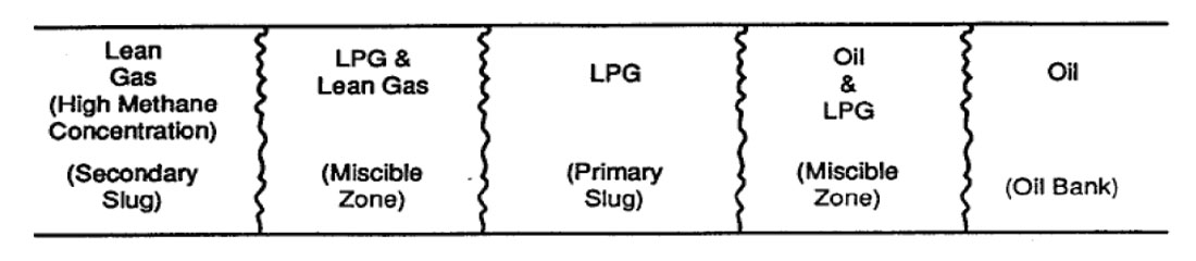
Enriched Gas Miscible Process. In the enriched gas process, a slug of methane enriched with ethane, propane, or butane (10 to 20% PV) and tailed by lean gas and/or water is injected into the reservoir. When the injected gas contacts virgin reservoir oil, the enriching components are slaked from the injected gas and absorbed into the oil.
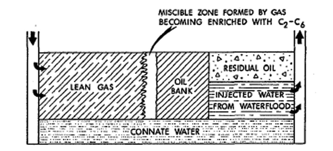
High Pressure Lean Gas Miscible Process. This process involves the continuous injection of high pressure methane, ethane, nitrogen, or flue gas into the reservoir. The lean gas process, similar to enriched gas, involves multiple contacts between reservoir oil and lean gas before forming a miscible bank. But, there is a difference in the enriched gas process where light components condense out of the injected gas and into the oil, then intermediate hydrocarbon fractions (C2 to C6) are stripped from the oil into the lean gas phase.
Carbon Dioxide Process. Oil displacement may be initiated by a number of mechanisms due to injection of CO2 into oil reservoirs. Carbon dioxide is not usually miscible with reservoir oil upon initial contact, however it may create a miscible front like the lean gas process. So, there are two major types of CO2 floods; miscible flood in which the gas is injected at or above the MMP, and immiscible flood in which flooding by the gas is conducted below the MMP. Miscibility is initiated by the extraction of large amounts of heavier hydrocarbons (C5 to C30) by CO2.
Chemical Processes. Chemical flood is another technique to increase the mobility of oil in order to enhance oil recovery. This technique is based on adding additives or chemicals to the displacing fluid or to the residual oil to control viscosity and interfacial tension. Chemical processes include micellar polymer flooding, caustic flooding, and polymer flooding.
Micellar Polymer Flooding. Micellar solutions are mixtures of surfactants, cosurfactants, electrolytes, hydrocarbon, and water. Surfactants are substances known as surface active agents, such as soap. Cosurfactants are used for stability such as alcohols. Electrolytes are salts used to control viscosity and interfacial tension such as sodium chloride or ammonium sulphate. Hydrocarbon used is light crude at most. These solutions, which are designed on a field by field basis, are proposed to displace reservoir oil and miscible water.
Caustic Flooding. An in situ emulsification process is employed by caustic or alkaline injection. The added chemicals to the injection water are caustic soda, sodium silicate, sodium carbonate, or sodium hydroxide. These chemicals are mixed with the residual oil in the reservoir. The crude oil must contain natural organic acids; most common are the naphthenic acids. When the alkaline injected water and acidic crude react, soaps are produced at the oil water interface. These soaps cause oil to be movable.
Polymer Flooding. Polymer floods a re improved waterfloods by increasing the viscosity of the displacing fluid which provides an increase in displacement efficiency. In addition, increasing the displacing fluid’s viscosity and lowering its relative permeability through plugging will improve the mobility ratio and this will make an improvement in areal and vertical sweep efficiency.
Thermal Recovery. Thermal recovery refers to oil recovery processes in which heat plays the principle role. The most widely used thermal techniques are in situ combustion, continuous injection of hot fluids such as steam, water or gases, and cyclic operations such as steam soaking.
Steam Injection. Heat is injected into a reservoir to reduce the oil viscosity and, consequently, to improve the displacement efficiency. As a result of improved mobilization efficiency crude oil is expanded and flows easily through the porous media toward the wellbore.
The process may involve steam soak that is sometimes called steam stimulation or “huff and puff”. In this process, steam is injected down a producing well at a high injection rate, after which the well is shut in. The injected steam heats up the area around the well bore and increases recovery of the oil immediately adjacent to the well. After a short period of injection the well is placed back on production until the producing oil rate declines to economic limits. The cycle is then repeated a number of times until no additional response to steam injection is observed.
Nitrogen Injection
As previously discussed one of the enhanced oil recovery methods is gas injection. In miscible gas injection, the gas is injected at or above the minimum miscibility pressure (MMP) which causes the gas to be miscible in oil. When flooding by the gas is conducted below MMP it is known as immiscible gas injection. Primary conditions affecting miscibility are: composition, fluid characteristics, pressure, and temperature.
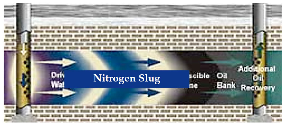
One gas employed for these gas injection techniques is nitrogen. Nitrogen has long been successfully used as the injection fluid for EOR and widely used in oil field operations for gas cycling, reservoir pressure maintenance, and gas lift. The costs and limitations on the availability of natural gas and CO2 have made nitrogen an economic alternative for oil recovery by miscible gas displacement. Nitrogen is usually cheaper than CO2 or a hydrocarbon derived gas for displacement in EOR applications and has the added benefit of being non-corrosive.
There are few known correlations to determine the MMP of nitrogen since the available literature data on the MMP of nitrogen with crude oils and synthetic oil are scarce. Nitrogen MMP of different oils is a function of the temperature, reservoir fluid composition, and pressure on miscibility.
Determination of the MMP of nitrogen with the particular oil is necessary to ensure the successful operation of the miscible flood. Therefore, research needs to be done to exemplify the process for determination of the MMP for nitrogen. Here we will briefly discuss the nitrogen injection process and the determination of nitrogen MMP. It is hoped in the future to develop a more accurate and reliable correlation for estimating nitrogen MMP which can be used as a screening tool to help decide if nitrogen miscible flooding is feasible.
History of Nitrogen
Over a hundred years after the discovery of nitrogen, a method to liquefy nitrogen was devised in 1883 by Wroblewski and Olszewski. Today commercial production of liquid nitrogen is obtained from the fractional distillation of liquid air. Air is liquefied by compression and progressive refrigeration at a pressure of 665 psi. and liquid nitrogen boils off at -320.45°F. Only quite recently materials and equipment have been developed to handle very cold liquids like nitrogen on a commercial level. The field of science that deals with the technology of handling liquids colder than -187°F is called cryogenics. All the liquids and the equipment to handle these cold liquids are considered cryogenic liquids and cryogenic equipment. Special steels and aluminium are the most widely used cryogenic construction materials; however, copper and bronze alloys are also used for specific applications (Dowell (1982), Barber (2005)).
Use of Nitrogen
The chemical industry is the largest user of industrial nitrogen. A large portion of its nitrogen use is for the manufacture of ammonia for fertilizers. Smaller users of nitrogen are the electronics, aircraft, refining, public utility, missile, and food processing industries. Recent developments with liquid nitrogen for food preservation show a strong growth potential for nitrogen use in this industry. Interest in nitrogen for oil and gas well stimulation work is focused on the compact source of high energy gas available at a reasonable cost. Without expensive compressor equipment, gas at 15,000 psi pressure is available for well stimulation use through liquid nitrogen and its cryogenic handling devices (Dowell (1982), Barber (2005)).
Nitrogen, when injected at high pressure, can form a miscible slug which aids in freeing the oil from the reservoir rock (Sarma, 1999) (See Figure 1.2 and 1.3).
Field Supply of Liquid Nitrogen
The location of plant facilities to manufacture liquid nitrogen is only limited by the availability of power; since the raw material is air. A liquid nitrogen plant will also produce liquid oxygen and other rare gases found in the air. Rail cars are available to transport liquid nitrogen from the plant to the end user or larger suppliers. This extensive distribution has a stabilizing effect on the market price. The rail cars and the truck transports used to transport liquid nitrogen are vacuum jacketed cryogenic tanks. An inner tank made of stainless steel holds the liquid nitrogen. The outer shell of mild steel provides an evacuated space for insulating purposes. The tanks are provided with pre s s u re release valves to release nitrogen gas as pressure builds up in the tank due to gas expansion by heat. Rail cars will hold 1,200,000 SCF of liquid nitrogen. Commercial truck tanks carry 7,000 gal of liquid nitrogen (or 651,840 SCF) (Dowell, 1982).
| Table. 01 | |
| Chemical Symbol | N2 |
| Molecular Weight | 28.016 |
| Triple Point | -345.9°F at 1.82 psig |
| Normal Boiling Point | -320.45°F |
| Latent Heat of Evaporation | 85.67 BTU/lb |
| Critical Temperature | -232.87°F |
| Critical Pressure | 492.3 psig |
| Specific Heat (Cp) 77°F | 0.447 1 BTU/(lb) (°F) |
| Specific Heat (Cv) 70°F | 0.3197 BTU/(lb) (°F) |
| Ratio of Specific Heat | 1.401 |
| Thermal Conductivity 60°F | 0.01462 BTU/sq ft hr(°F/ft) |
| Density of Saturated Vapor at 14.7 psia | 0.03635 Ib/cu ft |
| Specific Gravity of Saturated Vapor at 14.7 psia (air = 1.0) | 0.967 |
| Density of Liquid Nitrogen at Normal Boiling Point | 50.443 Ib/cu ft |
| 1 Ib Liquid Nitrogen | 0.1483 gal |
| 1 Ib Liquid Nitrogen | 13.81 SCF |
| 1 gal Liquid Nitrogen | 6.743 Ib |
| 1 gal Liquid Nitrogen | 93.12 SCF |
| 100 SCF Nitrogen | 7.247 Ib at -320.4°F |
| 100 SCF Nitrogen | 1.075 gal at -320.4°F |


Join the Conversation
Interested in starting, or contributing to a conversation about an article or issue of the RECORDER? Join our CSEG LinkedIn Group.
Share This Article