Summary
Conventional seismic reflection methods have been used with great success over the past decades to explore sedimentary environments for petroleum resources. To apply these same methods to mineral exploration in hardrock environments we need to adapt the time-tested seismic techniques developed for oil and gas exploration to the problems associated with a seismically reflective medium. In Canada, 3D seismic investigations focus on massive sulfide deposits, rich in copper, nickel and zinc. The petrophysical properties of common sulfide minerals indicate that sulfide ore would make a strong reflector of seismic energy however, modeling suggests that the scattered response from the deposit will be dominated by converted shear wave effects. Moreover, the directivity of the scattered signal will be strongly dependent on the shape and dip of the deposit, implying that 3D surveys are necessary to fully capture and characterize the response from sulfide mineralization.
Introduction
2D and 3D seismic surveys are used to great advantage in sedimentary basins for hydrocarbon exploration, making them the most important and relied upon tool in the petroleum industry. To extend this exploration method to the mining industry certain problems need to be overcome and the method adapted to suit the hardrock environment. The problems stem from the inherent heterogeneity of the media that typically host mineral systems; seismic signals are scattered in all directions, often obscuring the response from the sought-after target. Low signal to noise ratios and a lack of prominent marker horizons add to the difficulty of exploration.
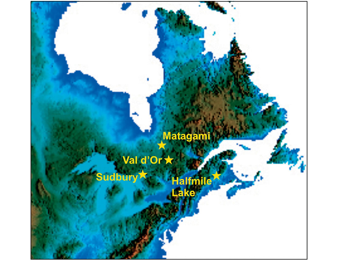
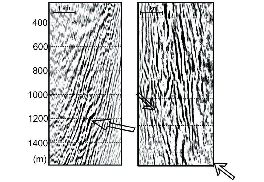
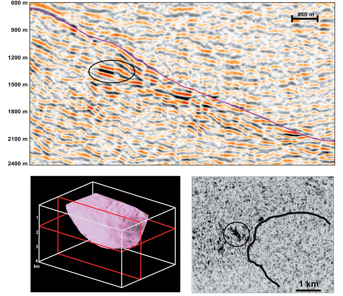
3D seismic surveying is now well established in the mining world through routine mine planning and development purposes. Some of the first examples include the seismic surveys to find the horsts and anticlines that might bring the gold and uranium bearing strata up to mineable depths in the Witwaterstand basin of South Africa (Pretorius et al., 1989). In the platinum mines of the Bushveld complex, South Africa, high resolution data are being used to map three dimensional geological structure and assess the size, geometry and distribution of mineable blocks; information that will be incorporated throughout the mine development and production phases (Duweke et al., 2002). In Canada, reflection seismology is currently being developed for base metal exploration (sulfide minerals – copper, nickel, zinc), where targets are deeply buried (500-2000m) high density contrasts. Ore deposits occur on all scales, however seismic methods are likely to be cost efficient only for bodies several hundreds of meters across. Tests of 2D and 3D seismic surveying have met with varying success: the Sudbury basin in Ontario, the Matagami and Val d’Or mining camps in Quebec and Halfmile Lake in New Brunswick (figure 1). The goal has been primarily to map structure or contacts between lithologies where ore deposits are known to accumulate. The Matagami project (figure 2) was successful in mapping structural elements and in locating and identifying the Bell Allard sulfide orebody. In Sudbury (figure 3), the 3D seismic survey allowed interpreters to map the known contact between the Sudbury Igneous Complex (SIC) and the brecciated rocks of the footwall, where most mined sulfide deposits have been found. Finding deposits deeper in the footwall has required data interpreters to shift focus from structural mapping to deciphering “bright spot” reflections deep under the surface. Both at Val d’Or and Halfmile Lake, the target areas lack any marker horizons and exploration is limited to mapping local reflections from possible sulfide targets.
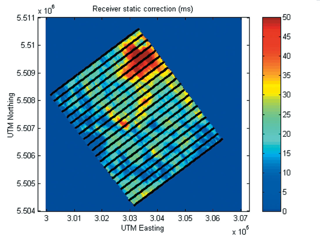
There are many problems faced in terms of adapting a technique that was developed primarily for hydrocarbon exploration for use in mineral exploration. During the acquisition phase, a more irregular shot-receiver pattern has to be adopted due to uneven terrain and inaccessible areas. The typical areal coverage for Canadian surveys is 20-30 km2, with 1000 shot points and 2000 live receivers. This gives rise to high fold, wide azimuth data, with resultant bin sizes of about 20 by 20 m. The uneven terrain and relatively thick overburden in addition brings up issues for static corrections which can be several tens of milliseconds in some cases. Figure 4 shows the receiver static corrections for the Matagami survey: with shot corrections of the same order, the total corrections can be up to 100 ms. Such large static corrections can introduce uncertainties of hundreds of meters in the high velocities (6000 m/s) characterizing hardrock terrains. In order to properly capture the response from a massive sulfide body, high frequencies (up to 120 Hz) are needed, but site access generally limits source type to dynamite or other explosives. Fortunately, there is evidence that massive sulfides reflect seismic energy in a way similar to the amplitude versus offset (AVO) response of hydrocarbons, which allows data processors to draw on the already well developed techniques of local bright spot detection and AVO analysis.
Challenge I: Seismic signature of massive sulfide deposits
Petrophysics of sulfides
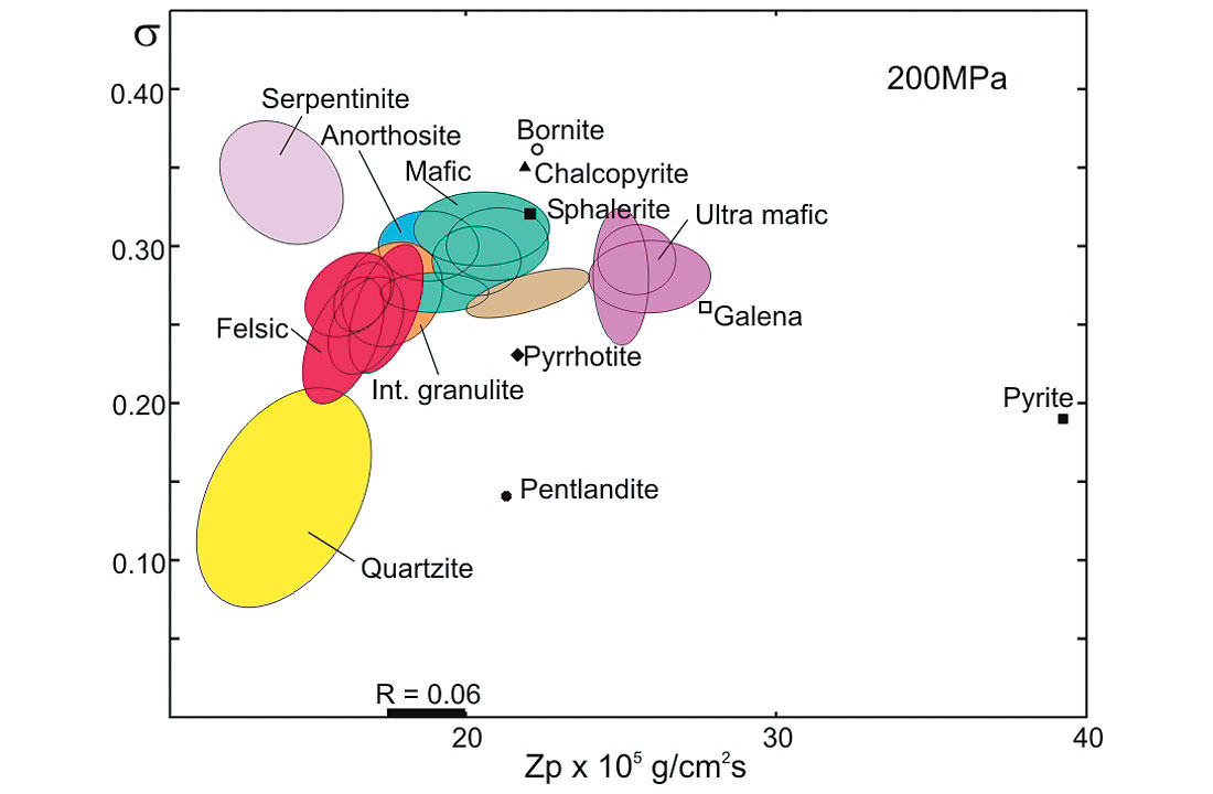
Crystalline rocks have average velocities that tend to increase with depth along the Nafe-Drake curve. Sulfide minerals on the other hand have high densities, placing them further to the right of the curve (Salisbury et al., 1996), within a large velocity-density field controlled by the properties of end-members pyrite (FeS2), pyrrhotite (FeS to Fe0.8S), chalcopyrite (CuFeS2) and sphalerite (ZnS). Velocities and densities within the sulfide field are further controlled by the mixing properties of the end-member sulfides and their host rocks. A mix of pyrite and felsic host rock increases in velocity with density, while ores containing chalcopyrite, sphalerite or pyrrhotite decrease in velocity with increasing density (Salisbury et al., 2003).
With the proliferation of physical property databases incorporating shear velocity information, we have seen that several rock types depart from the typical VP ~ 1.7 VS (σ = 0.25) pattern that describes most rocks (figure 5). Both VP and VS are unusually high for pyrite compared to most other sulfide minerals, causing many common mixed sulfides to have high impedances for both P waves and S waves. Since a coefficient of 0.06 (figure 5) is required to give a good reflection, most sulfide ores should make strong reflectors against common silicate rocks, provided they have the right geometric conditions for detection. The first challenge however is to distinguish between bright spot reflections caused by uneconomic mineralization – magnetite or pyrite rich ore. Many seismic sections indeed show a bright spot (see figure 3), but recent numerical modeling studies of sulfides have demonstrated that these deposits have a unique reflection character that depends on the deposit’s shape, size and composition (Bohlen et al., 2003).
The focus of seismic investigations has therefore shifted from mapping contacts to using 3D results to map and interpret the deposits themselves.
Forward modeling studies
Acoustic impedances imply that sulfide minerals should be strong reflectors of seismic energy in hardrock backgrounds (Salisbury et al., 2003). These media are typically described as seismically reflective or “transparent”, with small-scale heterogeneities causing the incident energy to be scattered in all directions. Well understood 1D or 2D wave equations are sufficient to describe wave propagation in homogeneous or stratified media, whereas in heterogeneous media more complex equations are required to describe the various regimes (characterized by scattering and the scale of intrusions). The heterogeneous nature of the medium causes the perturbations in density, P and S wave velocities to be large enough (~10%) that the simple wave equation can no longer be used for modeling wave propagation without significant error. 3D numerical simulations based on full wavefield finite difference methods are therefore needed to adequately describe the effects of the composition and shape of sulfide deposits on scattered seismic energy.
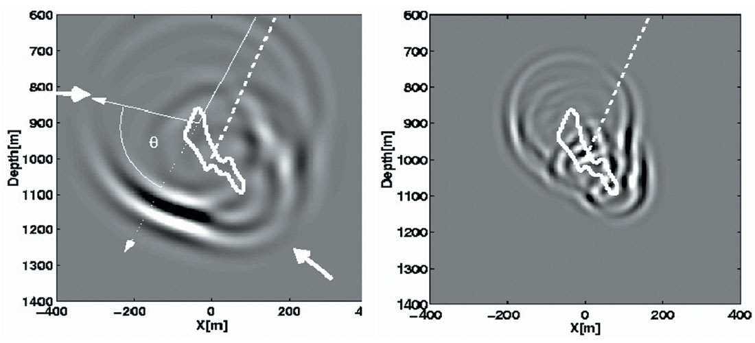
Current results indicate that large ore deposits lead to a strong and complex scattered response dominated by shear wave events (Bohlen et al., 2003). The shape of the ore has a first order effect on the directivity of both the P and S scattered wavefields (figure 6), whereas composition effects are often secondary. Massive sulfide deposits typically accumulate in veins or at contacts between different lithologies, often assuming elongate and lenticular morphologies (Eaton, 1999). Dipping lenticular bodies tend to focus scattered P waves in the specular direction, down-dip from the orebody (Bohlen et al., 2003; Milkereit et al., 2004). Strong amplitude variation with offset effects are likely to result from amplitude focusing caused by the shape of the deposit. Models also show that the composition of the scatterer produces predictable phase reversals and a dependence on azimuth of the reflected energy (Bohlen et al., 2003).
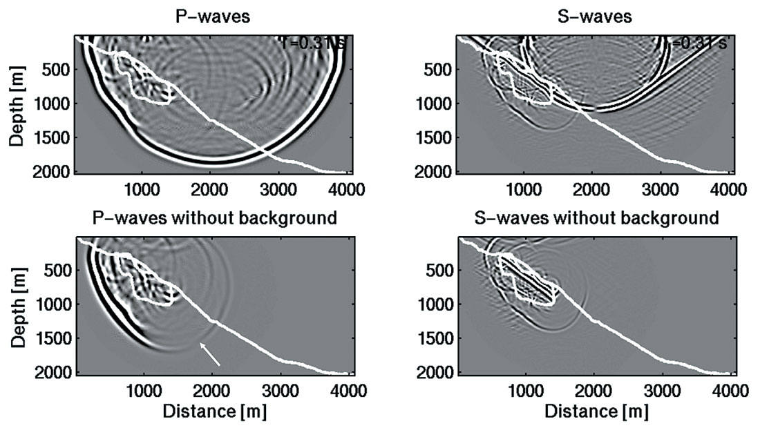
Because of the heterogeneous nature of the upper crust and hardrock environments typically hosting sulfide deposits, a more realistic model of seismic wave propagation has to include a non-homogeneous background. Initial results from simple models are shown in figure 7, designed to simulate a massive sulfide deposit along a dipping contact between two lithologies with varying degrees of heterogeneity. It is clear that the effects from small scale scatterers in the background obscure to a certain degree the signal received at the surface. The response from the orebody itself (figure 7 – lower) shows evidence of the same phase reversal in the scattered P-waves. As noted in the previous model, a significant proportion of the P wave energy incident on the sulfide body is converted to S waves.
Challenge II: Seismic data processing
The second challenge for seismic exploration programs is to establish processing schemes that enhance AVO trends and better define azimuthal variations. Over the past decade a limited number of studies have been conducted to investigate the applicability of seismic exploration methods to the mineral industry, among these are the Louvicourt mine (Val d’Or, Quebec; Adam et al., 2004), the Matagami mine in Quebec (Adam et al., 2003), Halfmile Lake in New Brunswick (Salisbury et al., 2003) and the Sudbury area (Milkereit et al., 2000). From these as well as the modeling results it is evident that through careful acquisition and processing of 3D data, the scattering response of massive sulfide deposits can be preserved. Provided the response is not completely obscured by any signal scattered by background heterogeneity, amplitude anomalies from sulfide orebodies will be recorded down-dip of the orebody and are often restricted to a limited azimuth range (Milkereit et al., 2004). Amplitude variations can be imaged through equivalent offset migration (Bancroft et al., 1998), which allows the data to be sorted and binned into ranges of offsets and azimuths, as depicted in figure 8.
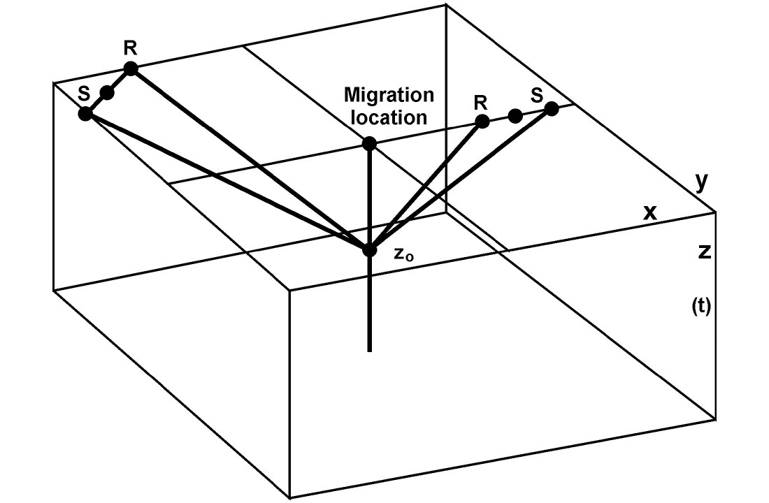
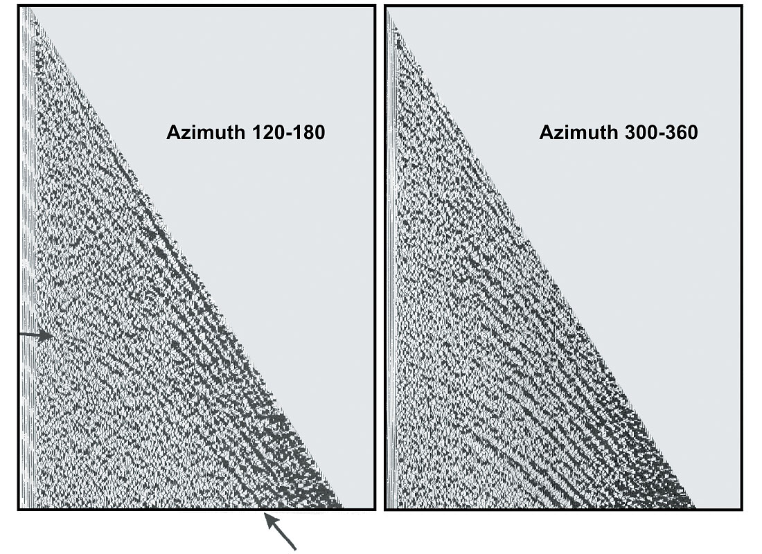
Figure 9 shows two equivalent offset gathers from the 3D seismic survey over the Matagami mining camp. The scattered response from the massive sulfides is best imaged in an azimuth range of 120-180°, while target stratigraphy is imaged in a range of 300-360° (Milkereit et al., 2004).
Conclusion
Mineral ore deposits are characterized by anomalous densities, P and S wave velocities. To fully model the response from these orebodies, comprehensive knowledge of their physical properties and a fully elastic algorithm are necessary. Accurate forward modeling using an elastic 3D finite difference algorithm has demonstrated the unique character of the seismic signals scattered off massive sulfide deposits, including amplitude variations with offset and azimuth caused by the deposit’s geometry and composition. Partial prestack migration techniques such as equivalent offset migration should be used to preserve relative amplitudes and enhance the response from the ore. Only 3D seismic reflection data allow us to study massive sulfide deposits by applying interpretation techniques geared toward enhancing the offset and azimuth dependent nature of the ore’s seismic response.

Acknowledgements
We acknowledge our collaborators Thomas Bohlen, Matt Salisbury and David Eaton for their contributions, as well as Alan King from Inco and Kevin Stevens from Falconbridge.


Join the Conversation
Interested in starting, or contributing to a conversation about an article or issue of the RECORDER? Join our CSEG LinkedIn Group.
Share This Article