Summary
Gaussian-beam depth migration is a useful alternative to Kirchhoff and wave-equation migrations in imaging geologically complex land areas. It overcomes the limitations of Kirchhoff migration in imaging multipathing arrivals and suffers no dip limits from one-way wave equation approximation. The accuracy of the Gaussian-beam method in solving the wave equation is, however, parameter dependent, limiting its applications in areas with strong near-surface structural variations. We describe in this study a complex-beam method which represents an improvement over the Gaussian-beam migration: It retains the advantages of the Gaussian-beam method over Kirchhoff and wave-equation migration, and is more robust in imaging complex structures. Applications of this method to field and synthetic data show that the new method produces depth images superior to those from Kirchhoff migration. It compares well to the reverse-time migration in imaging steep to overturned structures.
Introduction
Depth imaging of geologically complex land areas is challenging because of their steeply folded and faulted structures and because of their large lateral variations in topography and near-surface velocity. These difficulties are often further compounded by irregular data-acquisition geometries found in the seismic surveys from these areas. Prestack Gaussianbeam migration provides a useful alternative to Kirchhoff and wave-equation migrations for imaging these areas: It overcomes the limitations of Kirchhoff migration in imaging multipathing arrivals while retaining its flexibility with input geometry and topographic variations (Hill, 2001; Nowack et al., 2003; Gray, 2005; Zhu et al., 2007; Ting and Wang, 2008). Moreover, unlike wave-equation migration, which is based on a one-way wave-equation approximation, Gaussian beams are two-way solutions for the outgoing waves and hence have no problems in imaging steep to overturned structures.
Gaussian-beam migration also differs from Kirchhoff migration in that it takes into account the local slope of recorded seismic events and is a direction-oriented migration. While Kirchhoff migration treats seismic records as a collection of discrete samples and back spreads each sample onto its entire diffraction traveltime surface, Gaussian-beam migration models data as a superposition of local plane waves and back propagates each plane wave along a narrow beam in the initial direction specified by its local slope. As a result, Gaussian-beam migration spreads a recorded local plane wave only along a small beam front near where it is reflected, reducing migration swinging artifacts due to the imperfect cancellation of the spread energy by destructive interference.
The accuracy of the Gaussian-beam method in solving the wave equation is, however, controlled by a beam parameter, or, equivalently, by an initial beam width at the surface (e.g., Červený et al., 1982; Weber, 1988; Hill, 2001). This parameter introduces the needed smoothing in a geometric-ray solution so that the resulting beam solution will be regular everywhere. But in the Gaussian-beam formulation this parameter also determines how the width of a beam will evolve along its central ray. In the cases where the initial width is small, the width of a beam will increase rapidly along its central ray and becomes excessively large at deeper parts of the beam (Červený et al., 1982), which will in turn lead to inaccuracy in traveltime extrapolation along the beam fronts. This can be a problem for land data where near-surface velocity structures have strong lateral variations. The initial beam width in such cases must be sufficiently small in order to accurately image the shallow structures.
We have developed a complex-beam method for shot-domain prestack depth migration which overcomes the difficulties encountered by the Gaussian-beam migration. In this article, we describe this method and show its applications on both synthetic and field data.
Complex-beam migration
Similar to the Gaussian-beam migration method (e.g., Hill, 2001; Gray, 2005; Zhu et al., 2007), the complex-beam migration algorithm consists of two main components: local planewave decomposition of shot records and beam propagation and imaging of the decomposed plane waves. It differs from Gaussian-beam migration mainly in that complex beams, instead of Gaussian beams, are used for wavefield back propagation and imaging.
Local plane-wave decomposition
Figure 1 is a schematic 2D representation of local plane-wave decomposition of a shot record where S is shot location and R represents receiver locations. The decomposition begins by partitioning the record into overlapping Gaussian-windowed traces, each being centered on a regularly spaced grid point. These grid points are often referred as beam centres. Slant stack is then used to decompose each window of the tapered traces into local plane waves with a range of slopes, corresponding different initial propagation directions. The number of slopes is determined by a formula derived from wavefield sampling theory. Figure 1 shows one of these plane waves propagating from a Gaussian window centered on L. The width of the Gaussian windows is specified by an initial beam width at the surface, and the spacing between the beam centres is determined by the partition of unity of the overlapping windows (Hill, 2001).
Our algorithm for the local slant stack is flexible and capable of dealing with both regular and irregular trace spacings. Thus the algorithm provides an additional benefit in
performing a uniform spatial gridding or binning of irregular data, reducing the effects of acquisition footprint. Moreover, as anti-aliasing filtering is carried out as part of decomposition on the slant stacked data based on the slope of each local plane wave, operator anti-aliasing during the migration is no longer needed which is required by Kirchhoff migration. Standard formulation for migration operator anti-aliasing assumes horizontal reflectors and has been found to be detrimental to amplitude preserving of steep reflections.
Beam propagation and imaging
After data decomposition, each local plane wave from a beam centre is back propagated in our algorithm by a complex beam constructed around a central ray traced from the beam centre with a given initial direction (the blue solid line on right side of Figure 1). Similar to Gaussian beams, complex beams are local solutions to the wave equation and provide complex valued traveltimes and amplitudes for imaging. The two types of beam are, however, constructed in different manners and have different beam properties. A Gaussian beam is obtained by solving a parabolic wave equation along a given central ray (Červený et al., 1982); its beam width expands hyperbolically at a rate inverse proportional to the initial beam width. This property can, as pointed out earlier, lead to excessive expansion for a beam with small initial beam width and result in inaccuracy in imaging the areas with strong near-surface variations. A complex beam, on the other hand, is constructed by solving the wave equation with a complex source location in a ray-centered coordinate system (Zhu and Chun, 1994; Zhu, 2009). The small imaginary component of this complex location ensures that the beam solution is regular everywhere, and the real component is used in a perturbation scheme for calculating the wavefield in the neighbourhood of the central ray. The beam width is determined by the first Fresnel zone and increases along the central ray at a rate proportional to the square root of the initial beam width. Complex beams thus have no difficulties in handling rapidly varying near-surface structures since a smaller initial beam width will result in a narrower beam along the entire central ray and more accurate traveltime extrapolation along the beam fronts.
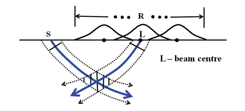
Similar to the wavefield at the receivers, the point source wavefield at S is also decomposed into local plane waves and propagated by complex beams with different initial propagation directions (Figure 1). A subsurface image is generated from the overlapping area between a pair of source and receiver beams (shaded area in Figure 1). Accumulating the contributions from all shot-receiver beam pairs for a given beam centre produces a beam-center image, and summing over all beam centers from a shot record gives a common-shot image. The final subsurface image is formed by stacking together all individual common-shot images.
Seismic waves are often multipathed in a complex velocity structure and the number of the arrivals in general varies from location to location. Retaining such multiple arrivals is difficult in a typical Kirchhoff implementation which computes traveltimes from each shot or receiver to subsurface points and stores these traveltimes in a table for later image accumulation. To accommodate the multiple arrivals, the traveltime tables from all shots and receivers must contain not only multiple entries of varying size at each subsurface point, but also information to ensure that traveltime interpolations are carried out between points on the same traveltime branch. As a result, Kirchhoff migration is typically single valued, selecting at most one traveltime that links shot or receiver to a subsurface point. By replacing the single Kirchhoff traveltime table from each shot or receiver location with multiple beam solutions, the full beam accumulation process described above provides a natural way for retaining all multipathing arrivals in a subsurface image. This, together with the robust behaviour of complex beams, makes our migration algorithm an accurate and flexible tool for depth imaging in geologically complex areas.
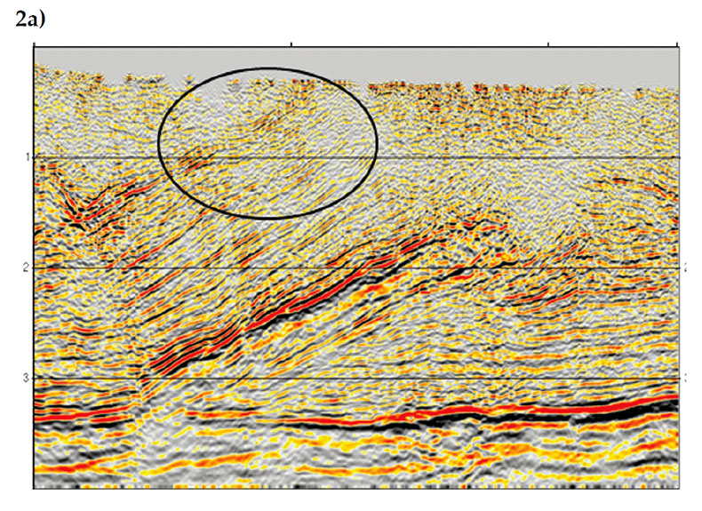
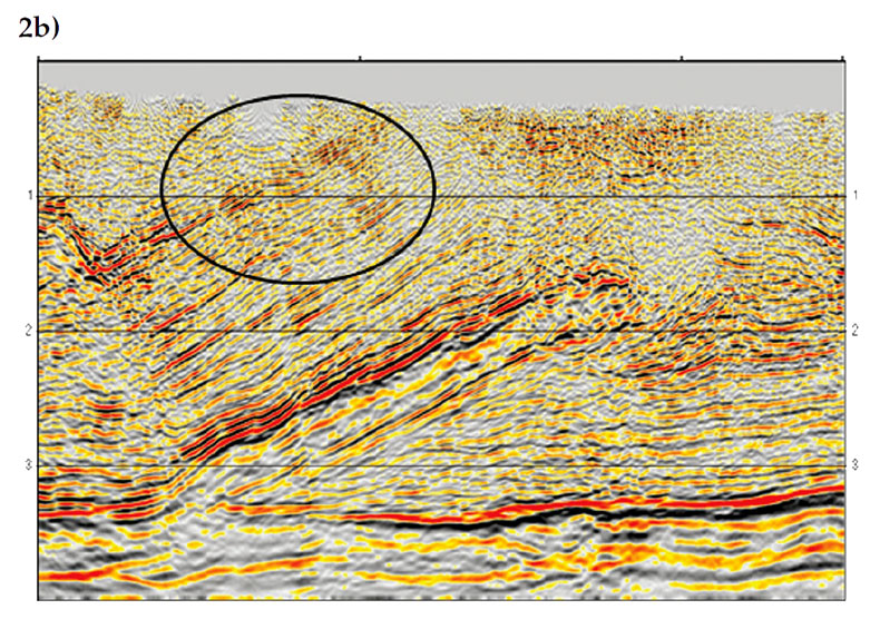
Examples The complex-beam migration has been tested with both field and synthetic data. The first example shows the results from a 2D Canadian Foothills survey which covers a thrust-belt area. The velocity model from this survey is anisotropic (TTI) and has strong lateral variation near the surface. The data was migrated using both Gaussian-beam and complex-beam methods and the results are displayed in Figures 2a and 2b, respectively. Both images are superior to that produced by Kirchhoff migration, as the Kirchhoff method was unable to image the multipathing arrivals generated by the complex velocity model (Zhu et al., 2009). A comparison of the two beam images, however, shows that the shallow part of the survey is better imaged by the complex-beam migration. The dipping events highlighted by the ellipse in Figure 2b, for example, appear more continuous and better defined than those in Figure 2a, showing that complex-beam is more robust for imaging structures with strong near-surface lateral variations.
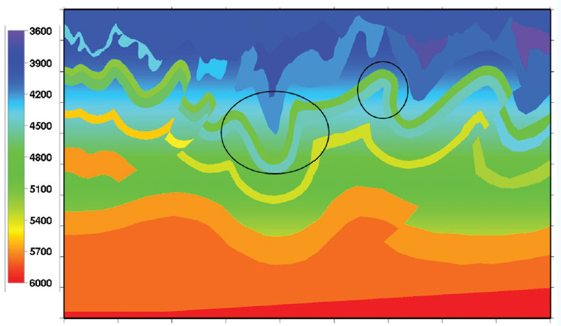
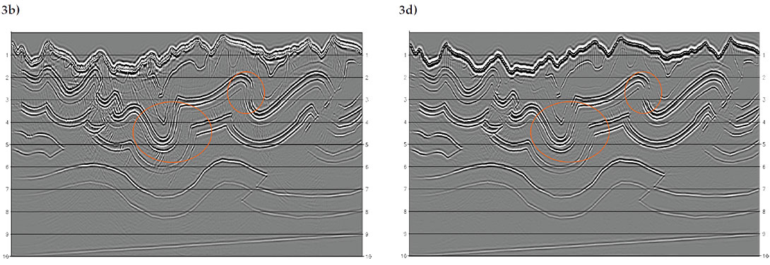
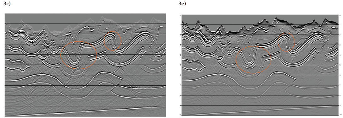
The second example compares complex-beam migration with Kirchhoff, wave-equation, and reverse-time methods using a synthetic dataset from the 2D Canadian Foothills model shown in Figure 3a. The model is about 25km long and 10km deep and is characterized by large lateral variations in both velocity and topography. The velocity ranges from 3600 to 6000 m/s and the maximum elevation difference reaches 1340m. It also contains steep and overturned folds as highlighted by the ellipses in the figure. Based on finite-difference solution to a two-way wave equation, reverse time is the most accurate migration method and its image in Figure 3b is used here as a benchmark for the comparison. For most parts of the model, all four methods give similar results. They all image, for example, the dipping basal reflector at the bottom of the model and the faulted fold about the reflector accurately. The Kirchhoff result (Figure 3c), however, shows more migration swing artifacts because of its wide-spread migration operators and because of its non-recursive implementation. It also failed to image the steep and overturned structures. The wave-equation image (Figure 3d) appears to be cleaner than other three, but it was also unable to image the steep structures due to its one-way approximation. Complexbeam migration (Figure 3e), on the other hand, compares well to the reverse time method and imaged both the steep and overturned structures correctly.
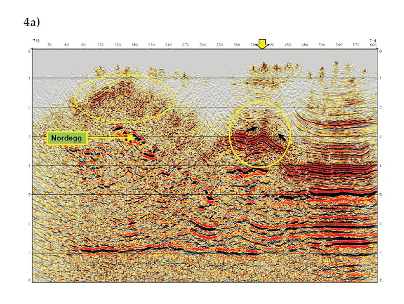
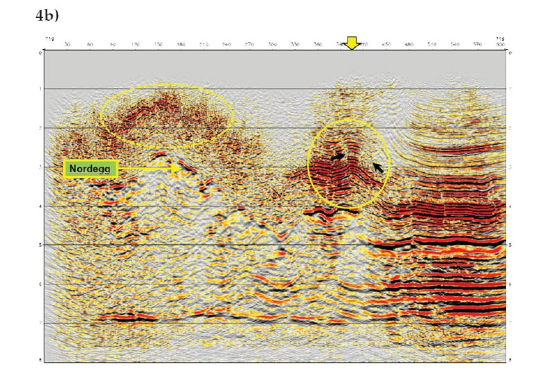
The final example is from a 3D Alberta Foothills survey. The survey covers a geologically complex area with a large topographic variation. The maximum elevation difference reaches 1240m. The data was migrated using both Kirchhoff and complex-beam algorithms with a TTI velocity model and the migrated sections on one cross-line are shown in Figures 4a and 4b, respectively. Compared to the Kirchhoff section, the beam image is in general cleaner and has less migration swinging artifacts. The solid yellow ellipse in Figure 4a, for example, highlights an area where migration swinging artifacts (indicated by black arrows) are relatively strong, and because of the interference of these artifacts, the events are poorly defined. The corresponding area on Figure 4b, on the other hand, has no visible swinging artifacts and the events are better defined and more interpretable. The dashed ellipses show another shallow area where events are more continuous and better resolved on the beam section. It is interesting to note that the Kirchhoff section below the Nordegg horizon appears to be noisier compared to the shallow part of the section, making the deep reflectors even less traceable than those on the beam section. One possible explanation is that multipathing arrivals are more prevalent below the complex overburden; not properly imaged by the single-valued Kirchhoff migration, some of these arrivals appear as noise in the section.
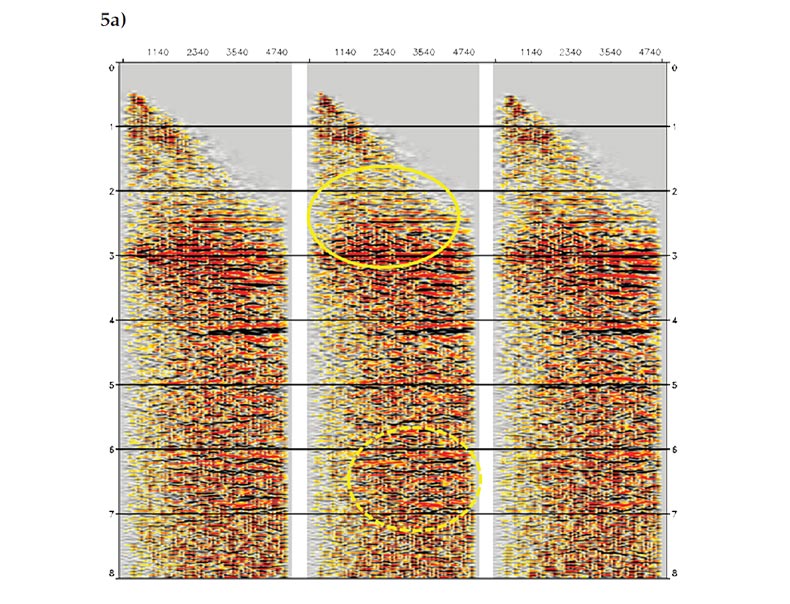
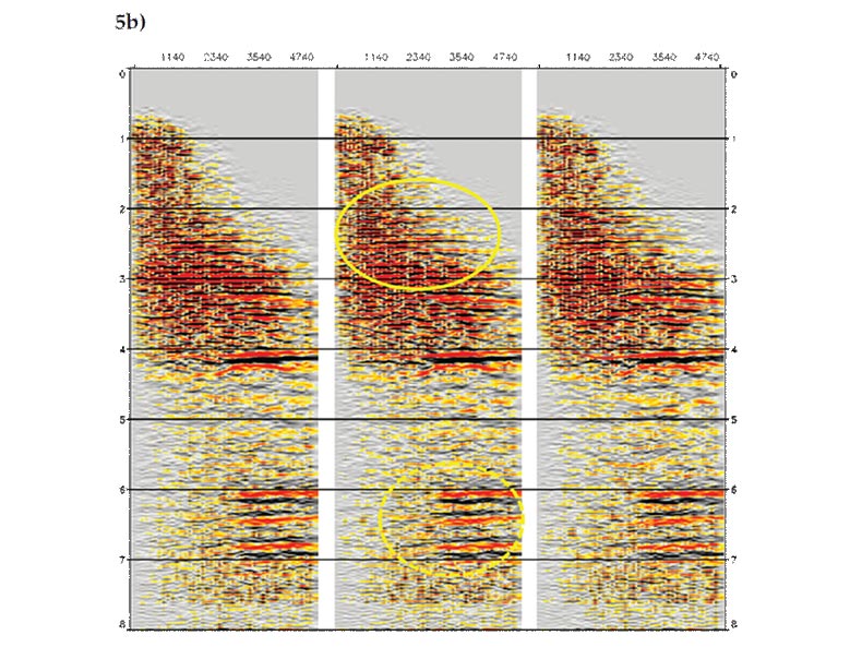
One of important applications of the Kirchhoff and beam methods is to generate various surface and subsurface common image gathers (CIGs) for migration velocity analysis. These gathers can be generated much more efficiently by these two methods than by wave-equation and reverse-time as ray and beam solutions contain all the local information needed for computing these gathers (Gray, 2007). Figure 5 shows one type of these gathers – common-offset CIGs – from three different CMPs near the location indicated by the yellow arrows on the tops of Figures 4a and 4b. Events are picked from these gathers and used as input to a tomographic inversion scheme for velocity determination (e.g., Zhou et al. 2003). A comparison between the complex-beam (Figure 5b) and Kirchhoff (Figure 5a) results shows that reflection events are much better defined on both shallow and deep parts of the complex-beam gathers. The solid ellipses, for example, highlight some shallow events which are well imaged by the beam method but are poorly defined on the Kirchhoff gathers. Similar to the migrated sections in Figure 4, the improvement of the complex-beam over the Kirchhoff method in signal to noise ratio is more noticeable on the deep part of gathers. The dashed ellipses, for example, indicate the deep events which can be clearly identified in Figure 5b, but are buried in noise and barely visible in Figure 5a. Thus more events can be picked up from the complex-beam gathers and picked up more robustly, which will in turn lead to more accurate velocity determination.
Conclusions
We have developed a complex-beam method for shot-domain prestack depth migration. Based on a complex-beam solution to the wave equation, this method represents an improvement over the Gaussian-beam method. It retains the advantages of Gaussian-beam over Kirchhoff and wave-equation migration, and is more robust in imaging areas with complex structures. Test results with both synthetic and field data show that the complex-beam images are in general superior to those produced by the Kirchhoff method. They are cleaner and have less migration swinging artifacts, and both shallow and deeper structures are better imaged on the beam sections than those on the Kirchhoff sections. The CIGs generated by complex-beam migration have much higher signal to noise ratio than those from Kirchhoff migration, providing more accurate information for velocity determination. The test results also show that the complex-beam method does not suffer the dip limitations of wave-equation migration and compares well to the reverse time in imaging steep to overturned structures. Thus the complexbeam migration provides an accurate and flexible tool for seismic depth imaging in geologically complex land areas.

Acknowledgements
We thank Sam Gray for discussions about Gaussian-beam and complex-beam migration and for the Foothills synthetic dataset. We thank Talisman Energy Inc. and Calgary Data library of CGGVeritas for the field data examples, Chuck Ursenbach for the synthetic data examples, and Sam Gray and Pam Nagarajappa for reading the paper.
Related Reading


Join the Conversation
Interested in starting, or contributing to a conversation about an article or issue of the RECORDER? Join our CSEG LinkedIn Group.
Share This Article