Introduction
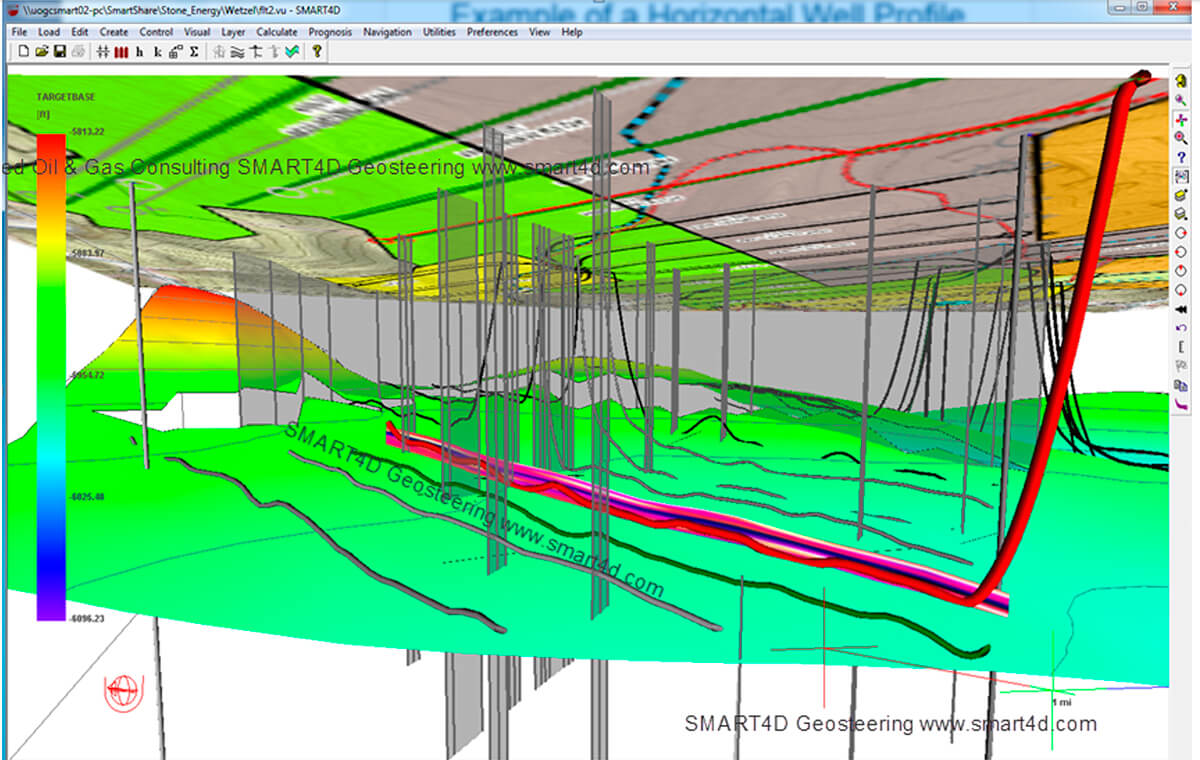
In geosteering, to dynamically and confidently drive forward with confidence in the target with minimum doglegs, we need to have a real-time solution that not only allows us to correlate to the last survey point (how we got here), but which also provides the latest calculated 3D path to where we are going on the well plans.
By examining previous G&G datasets and by real-time building 3D models of multiple structures and dips, thicknesses and rock properties, we can start the process. 3D interpretation needs to integrate at all times, all offsetting and real-time drilling data to create an immersive 3D pathway ahead of the surveys. This cycle-time between mappings has been reduced to minutes while drilling (WD), hence the 4D aspect of SMART4D.
SMART (System for Mapping & Analysis in Real Time) is a predictive learning model approach that adds efficiency and better workflow for operations teams, adding accuracy for landings and laterals by a proactive geosteering process.
True 3D modelling of variability in geology is currently underserved by 2D models. 3D workflows should not only be a requested feature of pre-drill models for geosteering, but demanded, since 3D variability is integral to geology and the nature of rock formations we drill.
SMART4D addresses several geosteering needs, not only in 3D interpretation, but also in team accessibility to the software through networks and the Cloud, as well as web-based reporting and rig data automations.

Previous software packages only solve the correlation element with a single vertical well at a time comparison with a TST (True Stratigraphic Section). While the TST method is useful, it creates a reactive geosteering process. It forces the geologist to place too many faults due to the software’s inability to handle thickness variations with single offsets. There are lateral variabilities that are not reflected using TST. There are also other approaches that suggest that they can model variable thicknesses. If examined more closely, these processes examine a TVD of the last log segment and look to themselves for matching purposes, filling in colors representing a gamma match. In the end, it is still a reactive 2D geosteering process.
Here is a driving analogy: No one drives forward looking into a rear-view mirror. Why should the drilling process work that way? We have solved this by re-creating an entire 3D interpretation by automating and optimizing 3D kriging to solve the path forward in about 5 minutes. The 3D kriging algorithm in the learning model with real-time data creates what we call a Dynamic Intelligence ® to drill with added confidence.
Reducing stress for operations geologists is part of this design. A driving analogy would be to suggest that if you know how severe the upcoming curvature on the road ahead is and the longer path to the final destination, you could confidently interact and plan a smoother path ahead. This process improves drilling with better way points as a result of just-in-time 3D modelling with the last few minutes of data; it results in reduction of doglegs (DLS) and tortuosity for every well drilled for both landings (16% reduction) and laterals (36%). Formation accuracy has improved, and all wells remain in their engineered sweet spots, improving the wells’ completions and ROIs. Faster drilling due to trouble-free and accurate placements has reduced rig days ranging from 18% to 36% and has added capital efficiencies for producers in the last 3 years.
Through over 20 years of R&D and over a 1000 wells geosteered through SMART4D, the collaborative process is bearing fruit for several operators. WITSML (Well Information Transfer Standard Markup Language) rig data retrieval and real-time web reporting tools and leveraging of cloud-based access to the process have added efficiencies and convenience for operations geologists and teams. Clear and powerful real-time panels, map views and 3D visualizations through the web and team communications provide the bridges for directional drillers and drilling teams.
The True 3D Model Approach
Optimized way points in the sweet spot of drilling targets, in tandem with the forward modelling of the 3D geology, have proven to minimize doglegs and tortuosity and can have a large influence not only on the completion of the well, but also on drilling safety and economics.
Our approach continuously provides updated 3D models that re-integrate all G&G datasets while drilling (WD), providing the proactivity needed when combined and influenced by incoming gamma log data through automation of rig data (WITSML). So when new gamma logs and surveys automatically stream in and are interpreted to be part of the zone of interest, they are fully included into the 3D model.
Geophysics Input
XYZ structure points from 2D and 3D seismic as well as incorporation of seismic profiles can be easily included in map views and SMART4D Panels.
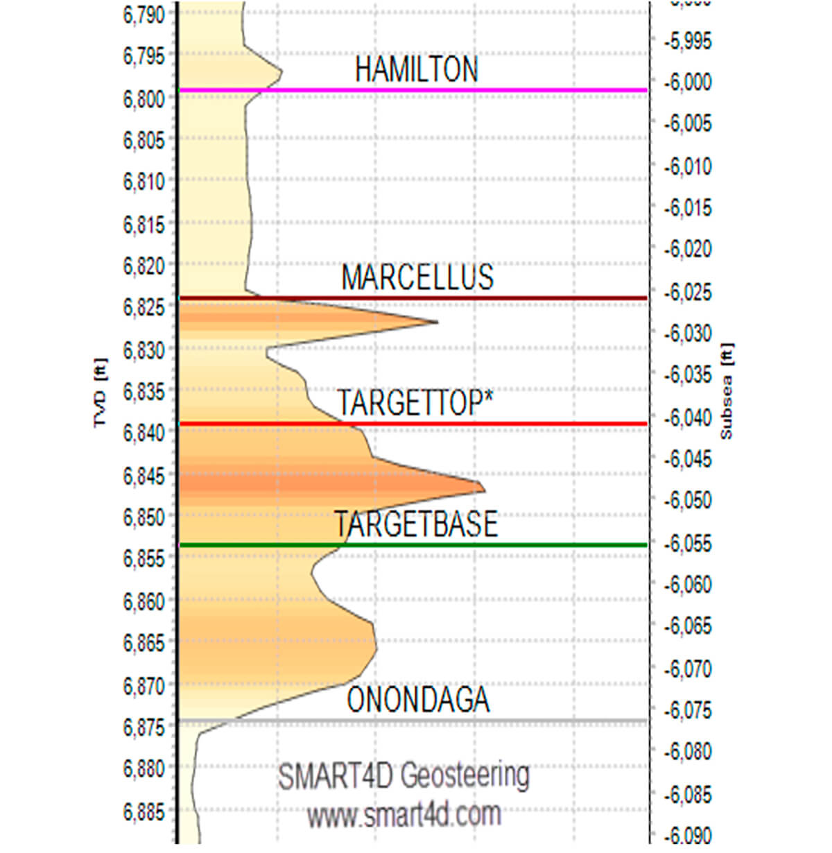
The seismic structures can be further used as a hanging structure for multiple other structures. For example, the underlying Onondaga structure from seismic can be used for the Marcellus and other units.

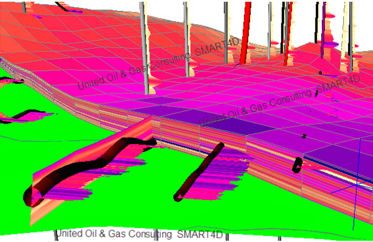
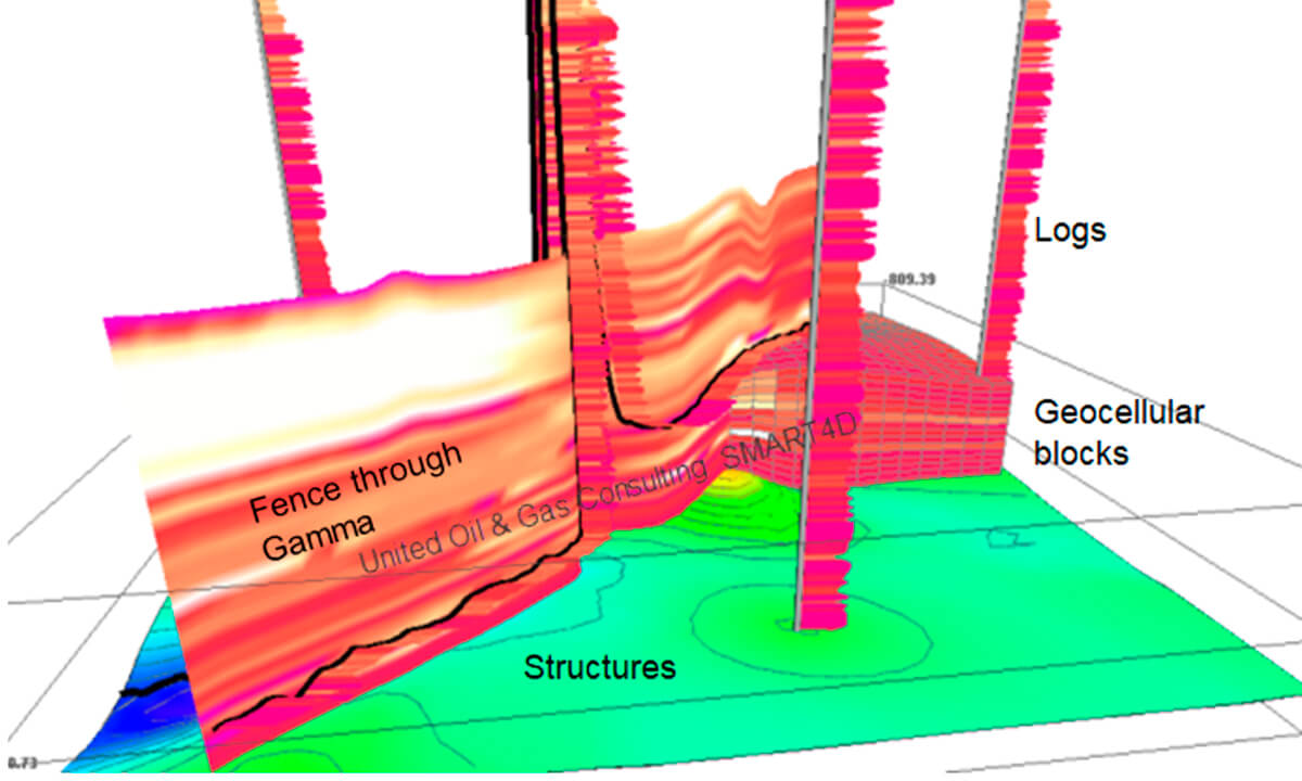
The mathematical geo-stat engine we use is 3D kriging. It has been automated to produce a solid model interpretation of rock properties such as gamma, porosity and resistivity, besides mapping related structural surfaces and isopachs/formation thicknesses, thereby enabling a monitoring of spatial data and geo-hazards such as potential faults and contacts with hard layers that can destroy bits rapidly.
Directional Drilling (DD) – Operations Geologist Collaboration
Focusing on the geosteering component pays high dividends on the ROI of a horizontal well. Collaborative interaction of the geologist’s way points and the directional driller’s (DD) inclination adjustment decisions in real-time (RT) have great influence on the optimal well placement. Historically we have been providing the least amount of information for the drillers driving the placement (from point A to Point B). Through inclusive delivery of proactive 3D model updates and clear panels that show the view of the drilling all the way to planned TD, DDs can have better drilling results.
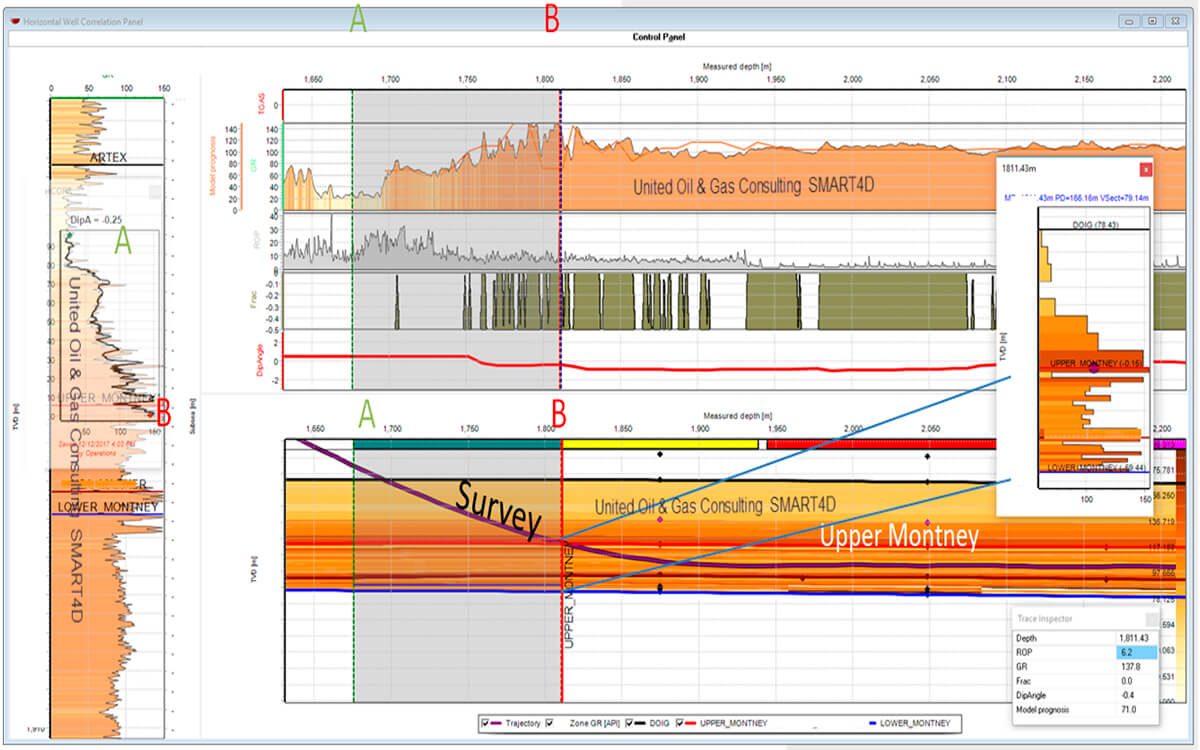
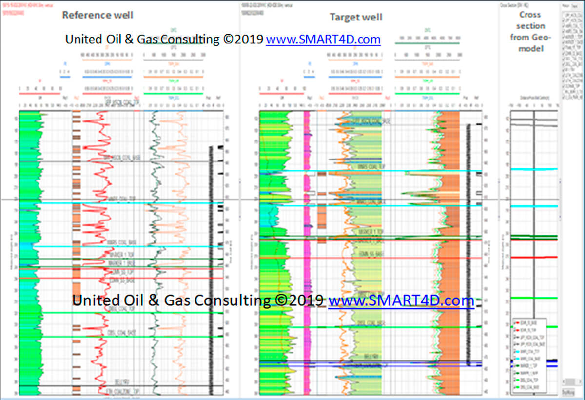
The StratCORR facility provides the clarity for understanding how we got to the latest landing position. However, it does not provide a forecast or prognosis of where we should be heading. Often the guess on the way point cannot be truly backed up and multiple solutions can coexist until resolved later. The analogy that no one drives forward looking into a rear view mirror holds, but a dynamic 3D model can help lead the way. While the well plan based on pre-drill geology/structure can suggest a potential plan to decide on a waypoint, the structures may in the short term do something different. Way points calculated from a continuously updated 3D model are more robust and show the 3D structures, thickness and rock properties changing before TD is reached.
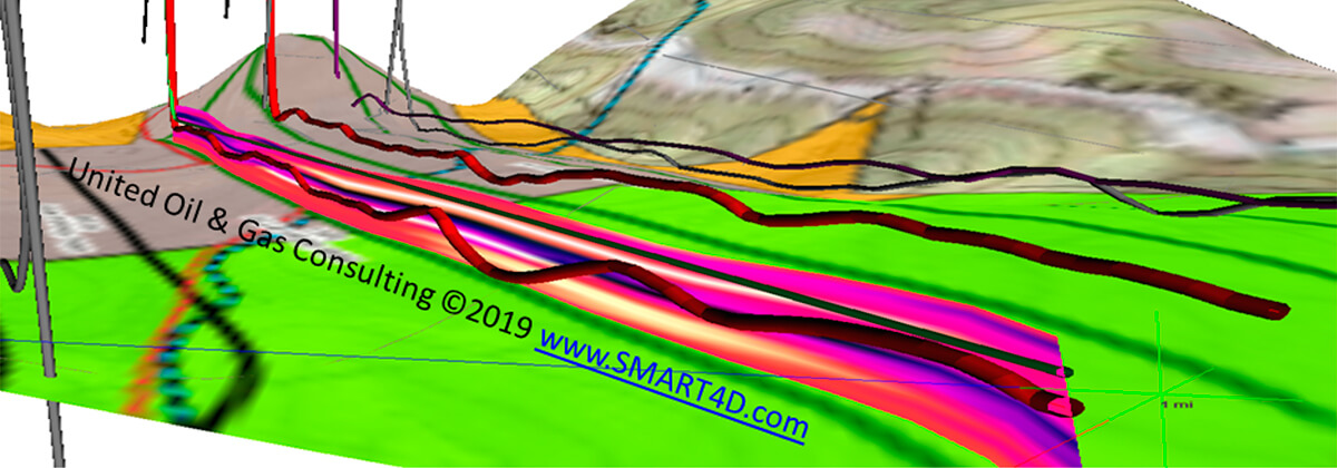
The only way to properly account for all offsets, multiple structures, and rock property changes is to model in 3D and update frequently.
Collapsing the Cycle time for Update of the Geomodel
For proactive geosteering to work optimally, frequent and rapid regeneration of the 3D model is necessary in real time. As drilling with rotary steerables (RSS) has become more common, improvements in drilling have increased ROPs dramatically. Precision has also increased, both in regard to survey corrections for magnetic variations as well as drilling ability to hit precisely set geometric target points.
The largest variability in a play is the geology, and it needs to be updated frequently. The old habits of “let’s drill and evaluate later” are not accepted by most oil companies or investors.
Engineered Targets
The majority of producers will do the required modelling of shale/tight oil or conventional plays before starting a large drilling program. Strat wells indicating the TOC, plus analysis of optimal geo-mechanical properties such as the Young’s Modulus, Poisson Ratio and brittleness/stiffness, help define the engineered frac interval. Poor placement can result in forfeiting reserves when we can’t complete the stages.
There are some producers that consider and execute large programs of over a 100 wells in various benches with geometric placements and little or no geosteering. While we recognise that spacing and orientation of wells in the XY direction is a geometric exercise, it must consider the newest geological mapping and older verticals and horizontals at multiple target levels while drilling.
The main issue is that if wells are geometrically steered without consideration of the most current geological understanding, we end up getting average to poor wells. In reality, results of drilling (after frac and early production) are typically in 1-2 years down the road. Doing the best technical practice all the time will ensure all wells are at peak potential and will reduce the decline rate, ensuring better economics.
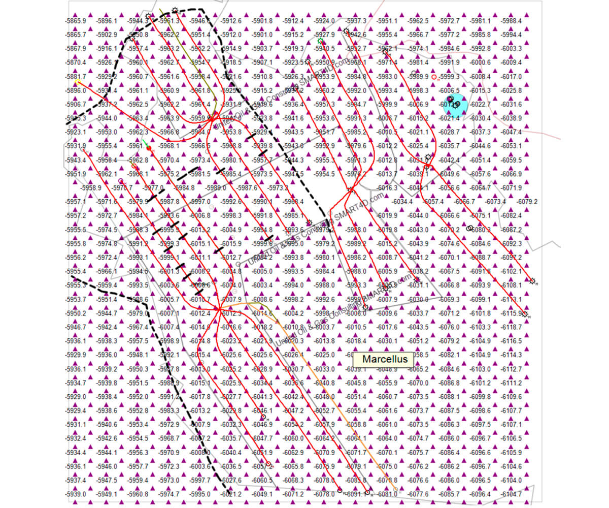
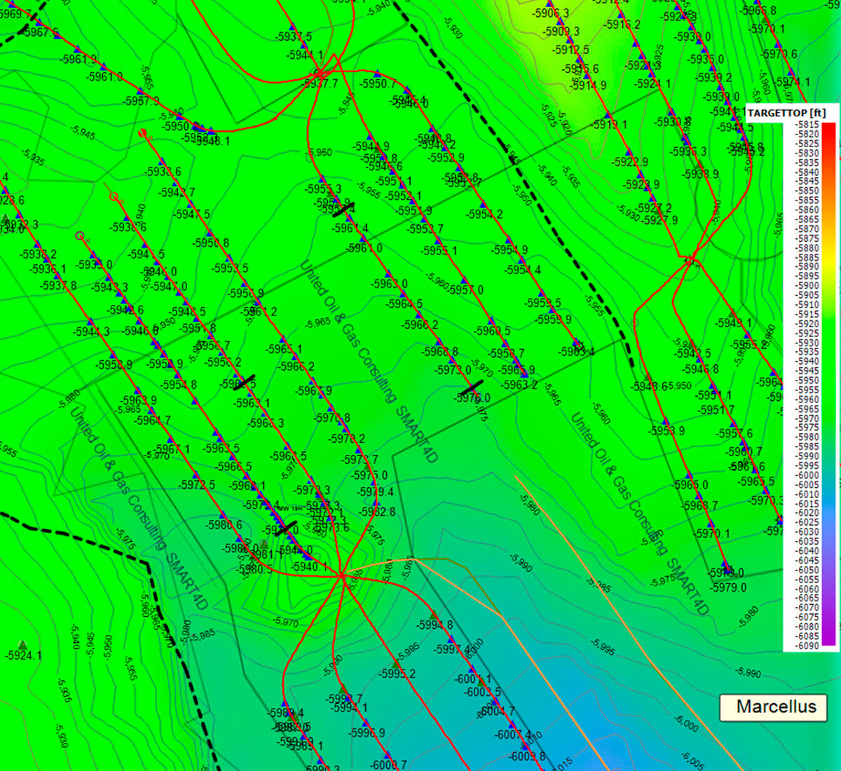
In our Marcellus Case Study, the client mentioned that although the total Marcellus is 50’ thick, outside the 12’ brittle interval of very hot gamma (up to 950) and high TOC, wells may encounter clay material, resulting in frac failures, wasted capital resources, more risk, and reduced recovery and IP.
Under the topic of engineered targets, we should consider well drainage and frac shadows that may create not only drilling safety issues but economic risk. This is discussed later in this article for completeness as Other Factors Beyond Geosteering.
Since new access or re-fracs in these bypassed areas/volumes are rare, the resource is left behind. To simplify the process, if a 5000’ lateral is expected to recover 200,000 BOE, even 4 fracs out of 40 (10%) results in 20,000 BOE. Some people would argue that the resource may eventually work its way into production; however, in tight plays, by definition, only the SRV is produced, and it may take decades to produce a fraction of the bypassed pay.
Current 3D Geostat Models and Their Usage in Geosteering
There are several well known full-fledged 3D models in use by geoscience professionals. They are all bulky, have a steep learning curve, and licenses are very expensive. Although the larger integrated 3D models are used in the pre-drill well planning process, they are not typically used for geosteering due to complexity of learning for the operations staff and difficulty to update frequently WD. In larger companies, the project geologists typically pass on the offset data and plans to operations geologists that in turn use 2D geosteering products (using the TST method).
SMART4D Geosteering, by contrast, is a highly interactive 3D-model-based geosteering process that continually uses all offsets to build/re-build a geostat model easily at a much lower cost than the large 3D systems (at 2D product price levels). Also, at any point of a drilling or field development, the model is always up to date and does not require reintegration of geosteerers’ post-drill solutions. We have had a couple of projects with more than one active rig drilling in different pads but in the same model areas, updating each other’s structures and 3D gamma properties in their path ahead of the surveys. There is also a QC component with the process for upcoming plans to see how they fit into the model.
Modelling Philosophy
The philosophy behind all processes in SMART4D are that they have to be simple and repeatable. The driving analogy is that most people who like to drive are not interested in how the piston moves in the engine. The idea is that every geoscience professional (geologist/geophysicist) should be able to build and update these 3D models with great ease.
We have reduced the 3D model initializations and collapsed update times to about 5 minutes by automating the rebuilding of a geo-model down to a single command. The learning model may also support another well or over 100 new wells. The setup for new drills is within minutes.
3D kriging was selected as one of the best 3D interpolation algorithms that considers all of the distance weighted datasets available in a project area.
The base map module also integrates raster images from other software and allows users to digitize structures on the fly to add more control.
Structural Control Points and Faults
Structural control points can be brought in from 3 main sources: tables of regular structure tops in measured depth (MD), other software (XYZ tables), or values digitized from the basemap or placed on the horizontal panel offsetting a wellbore. Structural control points can be generated from StratCORR or 3D seismic profiles. Faults can be introduced both on a map view and along the path of a horizontal well.
3D Kriging Automated
To make it work for all geoscience professionals, we used Ph.D. level geostatistics professionals to automate 3D kriging early on in our development process. The kriging algorithm is one of the most efficient deterministic interpolation engines. It incorporates all G&G offset datasets as defined by a project, it develops multiple 3D structures and thicknesses, and it models rock properties.
The automation includes all structural points from tops derived from geologists, earlier mappings, depth converted 3D seismic, and controlling “independent points” that offset a horizontal trajectory for every run. Although we use the TST method in selected segments for correlations and can switch to any vertical offset as we drill forward, the resulting independent data points (X,Y,Z) going back to the kriging process, the collection of structure points from 3 methods for one or multiple structures influences the final structures. Also the real-time gamma, for example, is incorporated back into the model and recalculated as a 3D rock property. A typical well’s geo-model is updated over 50 time while drilling. The automated runs can be triggered in different ways, including by a single click by the geologist. Each run takes about 1-5 minutes or less, depending on the number of multiple structure and rock property runs.
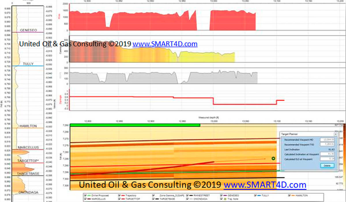
Proactive Geosteering and 3D Model Prognosis
The re-kriged 3D model delivers adjusted structures, thicknesses and rock properties that are delivered to real-time panels. Integrated panel projections are available and a target planner allows us to pick a way point ahead of the last survey to minimize doglegs. All operators are seeing a reduction in their doglegs and tortuosity when this process of new data integration, new correlations (StratCORR), and updates to the 3D models are frequently repeated.
Staying in thin engineered targets is critical, and agile placement solutions present improve landings and laterals where structural and lateral complexity is variable in 3D. The resulting solution is more unique than estimates from 2D processes.
Reducing Doglegs and Completion Issues
We have completed numerous post-drill studies to understand the underlying issues resulting in poor placements. Some wells reactively geosteered are poorly placed with too much doglegging and tortuosity, creating friction and kinks. Some of the post-drill studies showed high doglegs resulting in 30-50% of the lateral written off for completions, while some wellbores were not fracable in the toe segment of tight plays due to high doglegs.
Considering that fracs are very costly and failures result in lower initial production and recoveries, they need to be optimized. Poor lateral placement away from drilling plans may also result when true north corrections due to magnetic variations are not implemented while drilling. The precision is not only due to lease and survey accuracy considerations, but to correct spacing in multi-zone or bench drilling, such as in the Midland Basin within the Leonard, Spraberry, Dean and Wolfcamp packages. Any placement error laterally or vertically in the stack can influence the placement patterns for multiple zones. Our processes show reduced issues and better results.
Azimuthal Imaging
Although not a large percentage of producers run azimuthal tools, the trend is that we will see more of this in the geosteering workflow as costs decrease.
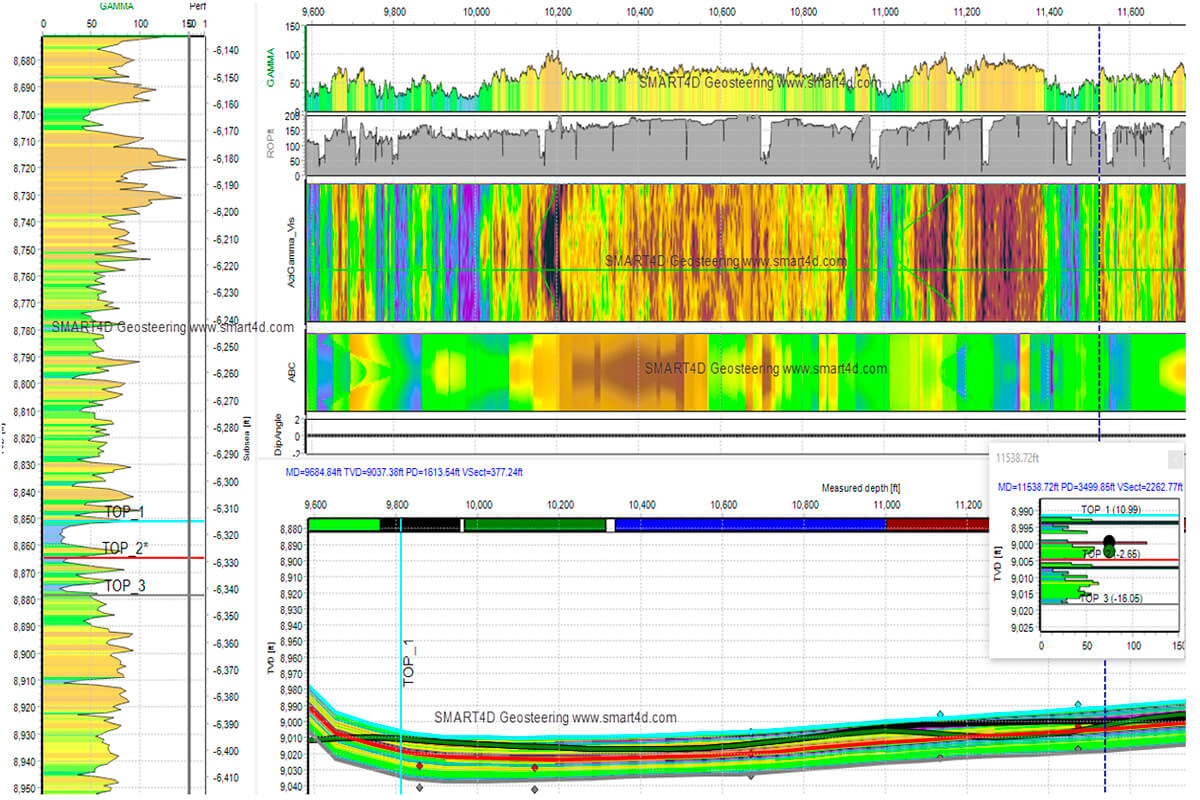
In SMART4D, we can integrate real-time rig data through WITSML (over 15 servers including Pason and NOV) or manual LAS files and produce a wellbore image to calculate dip and understand the placement better. Once data is loaded, the 2,4,8 or 16 tracks of azimuthal gamma can be transformed to develop an image of the wellbore, producing smiles and frowns as it goes up or down strata. Synthetic images can be extracted from any 3D property model in SMART4D, whether it is gamma, porosity or resistivity.
A Few Case Studies and KPI Improvements
In the WCSB Deep Basin plays in Alberta (Montney and other tight plays), COP/Cenovus drilled over 80 wells in a 2 year period, resulting in a significant 18% reduction in drilling days, 16% and 36% reduction in doglegs in the landings and laterals, and a 56% increase in formation accuracy. The operations team made use of gamma modelling in tandem with a porosity property model to optimize placement while drilling.
Black Swan Energy has drilled well over 50 wells; the client has reported “higher recoveries by staying in the target landing zone,” “consistently drilling entire laterals in 3m thick target zones,” “WITSML data retrieval allows for quicker response time,” and “high confidence in the well path interpretation.”
In the Powder River Basin, Sheridan Energy drilled 40 injectors, all placed in 10’ sand, and reduced doglegs in the laterals by 16%. The client reported a positive waterflood response.
Permian experience in the Delaware Basin (Eddy, Loving, Pecos and Reeves counties), the Midland Basin (Howard & Midland counties), and the Central Basin Platform (Ector county) is similar. Various Permian Basin clients such as SM Energy, Energen, OXY (over 300 wells), reduced rig-days from an average of 11 days to 7 days in a 150 well program, all with great landings and laterals. Over 100 wells in the stacked Permian plays with lots of structure were successfully placed by SM Energy using our approach, with great landings and optimized target placements.
Marcellus well placements for Stone Energy resulted in 100% well placements in 3500’ and 5000’ laterals in a 12’ high gamma target. Doglegs and tortuosities were reduced in the laterals by 27% and 35%, respectively. The client geologist explained that placement in the engineered high gamma sweet spot was important due to potential frac failures in the upper and lower high-clay material surrounding the sweet spot.
Other Reservoir Considerations Beyond Geosteering:
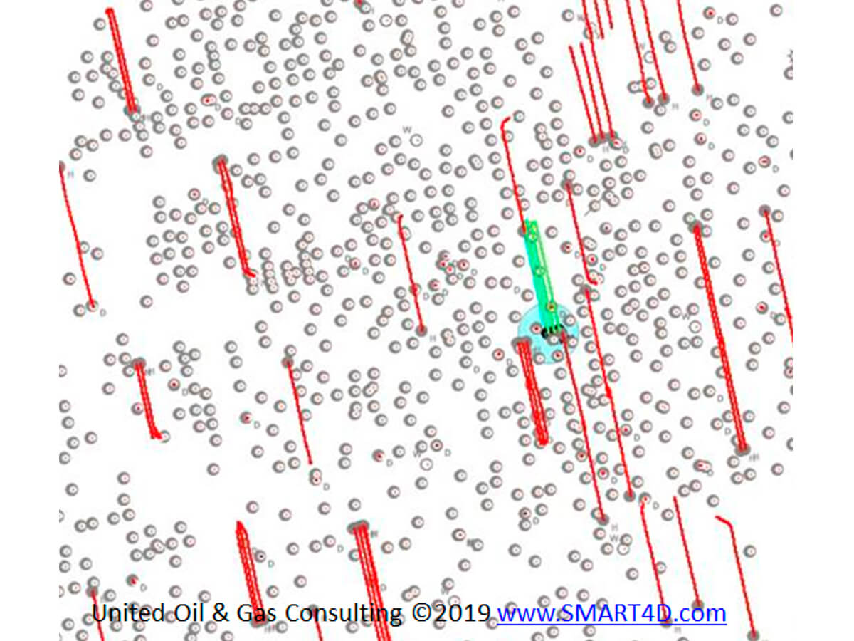
Producers can reduce technical and financial risk on well placements due to production (drainage of offsetting verticals, horizontals and their frac shadows) by some of the processes that we have developed for pre-drill studies.
Modelling the drainage volume of wells (SRVs) is an important reservoir engineering step that can reduce the risk of placement in low pressure areas associated with legacy vertical and newer horizontal wells and their fracs. This is useful for both well planning and geosteering.
Studies considering a few to a couple of hundred wells have been done using a technology developed by us called Volumetric Sweep Mapping (VSM), which models the recoverable volume of HCPV under a displacement efficiency (DE) in the wellbore path and fracs. The VSM simulator results have proven to be accurate, faster and more cost effective than full/dynamic simulators.
This VSM process will be explored further in a future paper.


Join the Conversation
Interested in starting, or contributing to a conversation about an article or issue of the RECORDER? Join our CSEG LinkedIn Group.
Share This Article