This paper describes the application of a new geomechanical workflow for modeling the interaction between hydraulic and natural fractures. The geomechanical workflow combines the meshless Material Point Method (MPM) with Continuous Fracture Modeling (CFM). The distribution of the natural fracture density is estimated from a time lapse 3C seismic that was processed for Shear Wave Velocity Anisotropy (SWVA). The resulting geomechanical workflow is used to predict the differential stress, frac stage performance and microseismicity. The predictions were validated with well and field data acquired in a Montney shale reservoir.
Introduction
The rapid growth of shale plays in North America has led to the extensive use of microseismic surveys which provide a unique insight in the complex process of fracing. Unfortunately microseismic still suffers from some serious shortcomings that are currently being addressed by many stakeholders. For example, the various methods used to acquire, process, and interpret the data sometimes lead to dramatically different results. Different service companies offer various acquisition strategies and the debate continues as to which one provides the best value. The differences in processing of microseismic data vary from one service company to another and the debate in this arena is more tumultuous. The end result of all these differences is a major discrepancy between the final microseismic products delivered by various service companies, each one insisting that their interpretation is the best representation of the events captured during the stimulation process. From the point of view of the shale operator these differences could make the use of these data very challenging. Hayles et al. (2011) illustrates this issue with a Bakken microseismic survey in which three very different interpretations were delivered by three different vendors. To reduce the uncertainties and improve the interpretation of microseismic data, many authors are using additional data derived from other sources.
One major data source that could help microseismic interpretation is 3D surface seismic and its subsequent attributes and seismically derived reservoir models. Using a Barnett example, Rich and Ammerman (2010) illustrates the effect of stress anisotropy and natural fractures on the resulting microseismic events. Hunt et al. (2010) qualitatively and quantitatively correlated microseismic events with the amplitude, AVAz, and velocity, VVAz anisotropies, curvature and coherency derived from the 3D surface seismic. They showed that microseismic exhibited a strong correlation with the natural fractures and could be used to map them. Refunjol et al. (2011) correlated multiple attributes, including curvatures, with the microseismic acquired in the Barnett Shale. Maxwell and Norton (2012) added the Poisson’s ratio to their structural attribute, to better explain the anomalous behavior of the microseismic events. Ouenes et al. (2014) correlated the microseismic with the seismically derived natural fracture density and the shale capacity models. All these cross-validation and co-rendering techniques help interpret microseismic events but do not provide a complete explanation of what happens during stimulation. When going down to the scale of the wellbore and examining the correlation between microseismicity and frac stage performance, many authors are encountering interpretation challenges.
Another important data source that could help with the microseismic interpretation is the production logs acquired along the wellbore. To the surprise of many shale operators, the production logs are showing that 30 to 50% of the frac stages are not contributing to production. For example Ganguly and Cipolla (2012) illustrate this dramatic variability with the production logs at four wells showing that many perforation clusters do not produce any gas, while a small portion of clusters produce most of the gas. Kok et al. (2010) used a production log to show the dramatic differences between similar frac stages, some stages contributing to 2.8% of the well’s production while other stages provided 19% of the well’s production. Now that most shale operators are recognizing this large variability in frac stage performance, how does microseismic help explain or predict this variability? Unfortunately microseismic interpretation is facing more challenges when used in conjunction with production logs.
Many published studies show a general trend where the high production of a frac stage is not necessarily correlated with high microseismicity. In other words, frac stages do not show a significant statistical correlation between microseismicity and production. An extensive study by Moos et al. (2011) shows an absence of correlation between the production logs and the density of microseismic events. Dick et al. (2013) published an interesting Marcellus case study where one of their laterals (4H in their Figure 5) shows the absence of microseismic events in about half the length of the lateral. Furthermore, the production log shows producing frac stages in the intervals where there is no microseismicity. When microseismicity is correlated to production it could be indicating water rather than oil production as shown by Martinez and Wray (2014) on a Bakken example. These challenges point to the fact that acquiring additional data such as tracers and production logs may not be sufficient to improve the microseismic interpretation and it could be that new technologies are necessary to make sense of all these apparently conflicting correlations.
Moving the microseismic interpretation from G&G to 3G
We may have reached a limit with our ability to interpret microseismic events by using traditional geology and geophysics (G&G). The complex process that creates the stimulated reservoir volume during the fracing process urgently points to the need to add geomechanics to the existing G&G tools in our microseismic interpretation efforts. Our chances to improve microseismic interpretation will most likely come by using 3G (geology, geophysics, and geomechanics) rather than G&G only. This is easier said than done.
Geomechanics could be used in different ways to help the interpretation of microseismic events. Two diverging routes are currently used in the industry. One route is the direct and explicit use of microseismic data in a geomechanical inverse problem. This approach uses microseismic as calibration data in an inverse problem that estimates frac design parameters (Maxwell et al. 2013, Palmer et al. 2013). A fracture network (most frequently estimated from microseismic) is adjusted to match a microseismic cloud and/or pumping data using an enriched frac design software. The level of enrichment of the frac design software vary from simplistic, where no natural fractures are accounted for (Palmer et al., 2013), to using a discrete fracture network (DFN) and a limited set of fracture propagation rules that control the behavior between hydraulic and natural fractures (Maxwell et al. 2013). This approach has many limitations due to its extensive reliance on microseismic data which remains a scarce soft source of data plagued by many acquisition and processing issues. Using data with large uncertainties as an input in inverse problems has been a major science and engineering challenge with no elegant and definitive solution yet.
The second route is a forward modeling approach that uses key reservoir inputs (structural properties, rock properties, regional stress fields, natural fracture distributions, and pumping data) in a mechanistic geomechanical model to predict microseismicity. (Aimene and Nairn, 2014, Aimene et al., 2014)). In this approach the microseismic data is not used as input in any computational process and its use is restricted to a comparison between the results of the geomechanical simulation with the available microseismic interpretation. Furthermore, this geomechanical approach provides multiple results that are beneficial to the understanding of the shale well performance at the detailed level of frac stages. For example, Aimene and Nairn (2014) were able to predict in a Marcellus well both the presence and absence of microseismicity along multiple frac stages. The benefits of this approach going beyond the prediction of microseismicity are illustrated by the possible correlations that may exist between the fracing energy and the production log at each frac stage (Aimene et al., 2014). These predictions of microseismicity and other geomechanical results stem from the use of a 3G perspective where the G&G data will provide the necessary input to a mechanistic geomechanical model which only requires as input structural properties, elastic rock properties, regional stress field, natural fracture distribution, and pumping data. To better illustrate this approach a Montney shale example is used.
A rich data set from the Montney Shale
A very rich data set acquired by Talisman Energy and extensively used by the Colorado School of Mines Reservoir Characterization Project (RCP) consortium will be used in this paper. This data set has been generating a large number of theses and publications that describe the various aspects addressed in the project. To the best of our knowledge, geomechanical modeling to predict microseismicity was not addressed in the past research and will be the subject of this paper. Actual data was not available to conduct this geomechanical work and all the information required for the geomechanical simulation was extracted from the theses, papers and their figures. A description of the available data and different topics addressed in the research effort can be found in Duenas et al. (2014) , Lee et al. (2014), Andersen et al. (2013), Grossman et al. (2013), Steinhoff (2013), Davey (2012), and Atkinson and Davis (2011). A brief summary of the available data is given below.
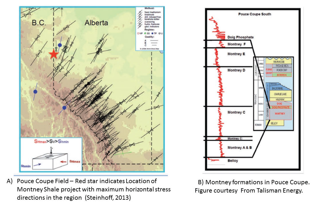
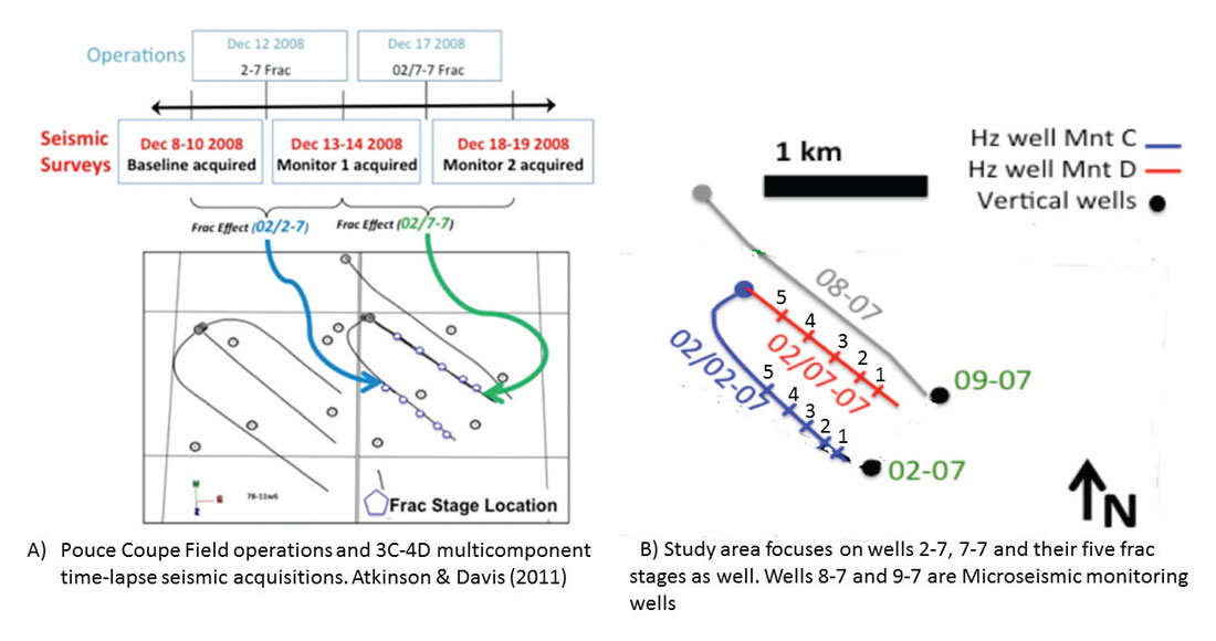
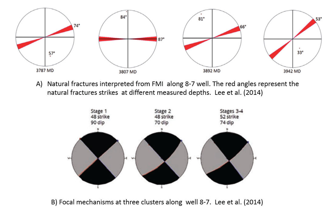
The study area is called the Pouce Coupe field located in Northwest Alberta and the target formation is the Montney shale which has been divided in six sub-units labelled from A to F. (Figure 1). One of the major characteristics of this study is the availability of a 4D multicomponent seismic survey that was acquired in December 2010. A two well pad is the focus of the study. Well 2-7 is completed with five frac stages in the lower Montney C while well 7-7 is completed in the upper Montney D also with five frac stages (Figure 2). Sliding sleeves with same proppant concentration and pumped volumes were used in both wells. Prior to any stimulation of the two key wells, a baseline 3D multicomponent surface seismic survey was acquired. This first survey was followed by two time-lapse 3D multicomponent monitor surveys, the first after the hydraulic fracturing of the well 2-7 completed in the Montney C and the second after hydraulic fracturing of well 7-7 completed in the Montney D. Microseismic data were acquired to monitor the stimulation across the five stages completed in each well. Three-component toolstrings were placed in the vertical well 9-7 as well as in the horizontal well 8-7 completed in the lower Montney C (Figure 2). In the horizontal well 8-7, a 10 sonde string was placed in the heel and a 50-sonde string was placed in the 9-7 vertical well. The 50 receivers in the 9-7 wells were spaced at 15 m meaning an overall vertical coverage of 735 m. Out of the 50 receivers, only the bottom two receivers were within the Montney zone. An observation bias leads to a greater number of microseismic events resulting from the stimulation of 7-7 especially towards the toe because of the relative position of the two monitor wells. Last but not least, spinner production logs (Figure 3) provided the contribution of each frac stage to the total first year gas production which was 19,884 m3 in the 2-7 and 14,074 m3 in the 7-7. The maximum horizontal stress direction is about N40E and due to the proximity to the Rockies a high stress anisotropy of 1.8 is observed in the study area. The stress regime allows a strike-slip failure since the maximum horizontal stress is greater than the vertical stress which in turn is greater than the minimum horizontal stress. An FMI log was available in the horizontal 8-7 well and its interpretation lead to the identification of four natural fracture orientations ranging from 53 to 87 degrees as shown in Figure 4. This rich data set is used in a geomechanical workflow to predict microseismicity and derive a better understanding of the resulting stimulation results and their effects on the well performance.
A new powerful geomechanical workflow to improve shale completions
A new geomechanical workflow was recently introduced to the oil and gas industry (Aimene and Nairn, 2014, Aimene et al. 2014) to improve the understanding of shale stimulations. The new workflow was validated with multiple field data where microseismicity was predicted. This field-validated achievement was possible thanks to the introduction of new elements that solve many problems that previously hindered the wide application of geomechanics to shale well stimulations. The two major features in this new workflow are the use of the Material Point Method (MPM) as a computation tool to model the interaction between hydraulic and natural fractures (Aimene and Nairn, 2014) and the use of the Continuous Fracture Modeling (CFM) (Ouenes, 2000, Jenkins et al. 2009) approach to model the distribution of the natural fractures that will interact with the hydraulic fractures. The new geomechanical workflow is fast and could be incorporated in the current frac design processes by helping the completion engineers answer a multitude of critical questions. The key deliverables of this workflow are illustrated with the considered Montney shale example.
The inputs listed above from input 2 to input 4 were available in published theses and papers and the big unknown remains the distribution of the natural fractures (input 1).
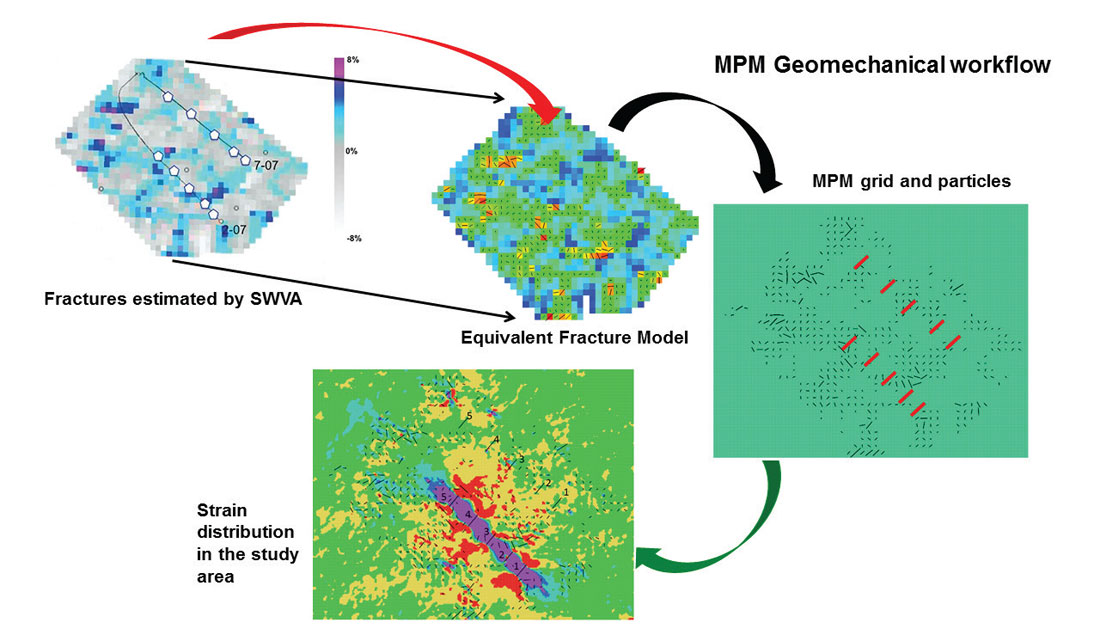
In previous field validations for the new geomechanical workflow the natural fracture distribution was estimated by using a seismically derived structural attribute such as coherency or volumetric curvature (Aimene and Nairn, 2014, Aimene et al. 2014). Despite the numerous theses and publications devoted to the Pouce Coupe field, we could not find any published seismically derived structural attribute. As a result, we had to focus on the Shear Wave Velocity Anisotropy (SWVA) results provided by Steinhoff (2013), and Grossman et al. (2013). By examining the results of the SWVA evolving from the baseline survey to the final time lapse acquired after the completion of well 7-7, it appears that the stimulation of the 2 wells is primarily revealing the presence of the natural fractures. The final SWVA map (Figure 3) shows features that could represent small faults which could be easily verified with a seismically derived structural attribute such as volumetric curvature if it was available. In the absence of this confirmation, we will assume that the last SWVA map derived after the stimulation of well 7-7 is a reasonable proxy for natural fracture density distribution. The fracture orientations are derived by using the SWVA map as input in the CFM approach to create the Equivalent Fracture Model (EFM) shown in Figure 3B. The EFM resulting fracture orientations computed in this work from the SWVA map are similar in orientation to those seen in the interpreted FMI log of well 8-7. This validation between the EFM fracture orientations and the actual FMI orientations supports the assumption that the last SWVA map (Figure 3A) is a good proxy for the distribution of the natural fractures density.
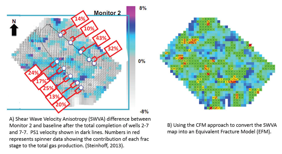
The fracture orientations derived from the shear wave velocity anisotropy (Figure 3A) show a dominant North South orientation tilting slightly by 20 degrees to the East in the Southern part of the survey. These estimated shear wave PS1 fracture orientations are in contradiction with the well 8-7 interpreted FMI data showing a dominant orientation in the Northeast and East-West directions. The PS1 fracture orientations shown in Figure 3A are not used in any part of the geomechanical workflow described in this paper.
The resulting EFM model is input in the MPM geomechanical workflow as shown in Figure 5. Prior to any stimulation, the effect of the regional stress on the naturally fractured shale reservoir is simulated to represent the initial conditions occurring before fracing the wells. Following this initialization step, the hydraulic fractures are added to the natural fractures described in the EFM model and pressurized sequentially as carried out in the field operations. The MPM geomechanical workflow provides multiple outputs discussed in the next sections.
Predicting the differential stress prior to drilling and fracing
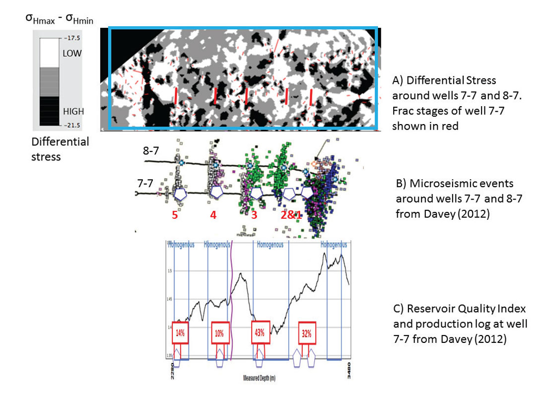
A major output of the MPM geomechanical workflow is the distribution of differential stress that is the result of the application of the regional stress on the naturally fractured media (Figure 6). This output is critical to the completion engineer because it will have a large impact on the success of the fracing of each stage and could give a sneak preview of the type of microseismicity that will be observed at that frac stage when stimulated. Under the same fracing conditions the success of a frac stage will be higher if the fraced interval is selected in an area of low differential stress. Most of the time these low differential stress areas tend to show diffuse microseismic events that are very often an indication of a large SRV and a successful transformation of the fracing energy into a rubelized rock. Zones with high differential stress need to be avoided since they tend to produce poor frac stages that are most of the times indicated by linear microseismic events that could mean a poor transformation of the fracing energy into a small SRV. To better illustrate all these concepts, a zoom in the blue rectangle in Figure 6 will focus on well 7-7.
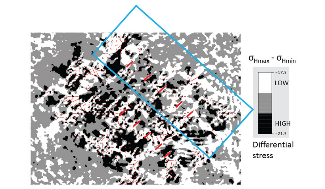
Figure 7 shows the differential stress near well 7-7 and 8-7, the microseismic events recorded at well 7-7 and 8-7, as well as the production log showing the contribution of the frac stages of well 7-7. It is important to note that 75% of the well 7-7 production comes from stages 1 to 3 where it is clear that the differential stress is low. The large number of microseismic events and their diffuse nature (Figure 7B) also supports this low differential stress result. On the right side of frac stage 4, the differential stress map predicts a high differential stress band similar to the fracing barrier described by Davey (2012) and shown as a purple line in Figure 7C. Davey (2012) defined the Rock Quality Index (RQI) to quantify, along the wellbore, the effect of brittleness and differential stress on a good and bad zone. Her RQI log shows many similarities with the differential stress map, which does not use any log data. Finally, the differential stress map clearly shows a higher differential stress zone on the left side of frac stage 4 that is confirmed by the production logs where only 25% of the production is coming from frac stage 4 and 5 and where the microseismic events tend to become linear.
The examination of the differential stress map along well 7-7 shows the multiple benefits of the MPM geomechanical workflow which could be used prior to drilling or stimulation. Prior to drilling, the drilling and completion engineer could adjust the position of his wells to avoid high differential stress areas. Prior to stimulation, the completion engineer could selectively skip or alter his design in some high differential stress zones along the wellbore where the fracing will most likely not be very successful with the considered pressure. The next step is to predict microseismicity and estimate the success of each frac stage from the geomechanical simulations.
Predicting and validating microseismicity where available
The major problem with the microseismic interpretation being discussed is the distance bias described earlier. The lack of seismic events is not necessarily an indication of lack of microseismicity but could simply be a consequence that the distance to the monitoring wells is too far, or that the orientations of the natural fractures do not allow for slippage and shearing. For example, the microseismic events for well 2-7 suffer from this bias and a limited number of events are available North of the well. The number of events south of well 2-7 is very low due most likely to their distance to the monitor wells. If we were to judge the success of a stimulation based only on microseismicity, how would one interpret the performance of well 2-7 stimulation given the distance to the monitor wells? The reality is that microseismicity can tell us nothing about well 2-7 because it is far from the monitor wells thus the need for the MPM geomechanical workflow to predict the microseismicity and understand the success of each frac stage.
The MPM geomechanical workflow used the derived EFM to represent the natural fractures that will interact with the five hydraulic fractures of well 2-7 once they are pressurized with the pumping pressure. The resulting strain has shown in previous field studies to be a good proxy for microseismicity. The limited microseismic events available North of well 2-7 could be used to validate the predicted microseismicity shown in red or high strain values in Figure 8. Since the number of events is not representative of all the possible shear slippage occurring near well 2-7, we will focus on the key features of the limited events. For example the microseismic events at frac stage 5 (green dots near frac stage 5 of well 2-7 shown with an arrow) show a V shape that is also predicted by the strain map. Another way to validate the resulting strain map is to use the available production log at well 2-7. The lowest contribution in this well is 13% which was measured in frac stage 2. The lack of microseismic events at well 2-7 imposed by the far distance to the monitor wells does not provide a convincing explanation for this low contribution. However, the predicted strain map which could serve as a proxy for microseismicity shows an obvious poor stimulated area (lack of high strain values around frac stage 2).
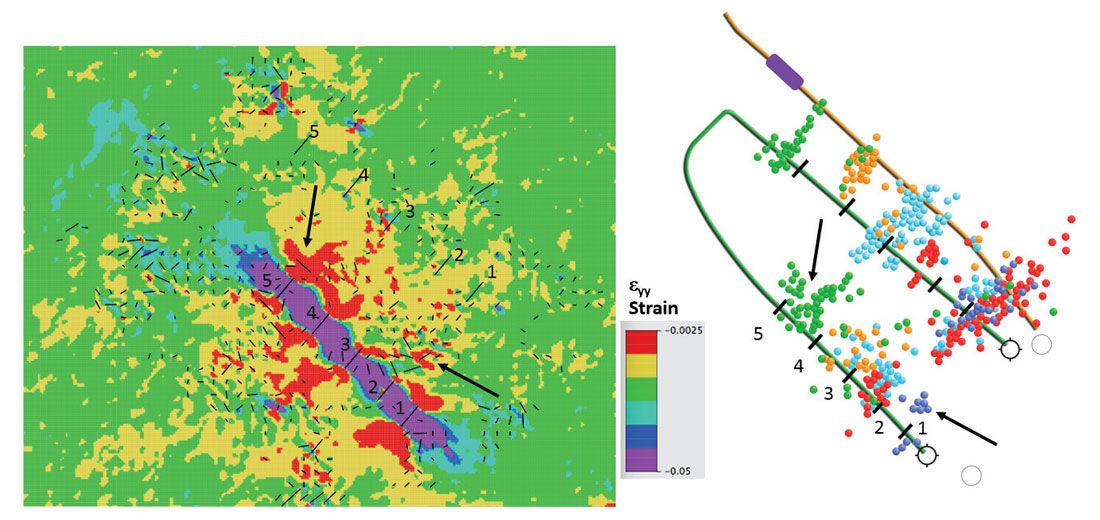
From the predicted strain around well 2-7, one can estimate the asymmetric fracture lengths at each frac stage. It appears that the Southern frac length at stage 3 and the Northern frac length at frac stage 5 are the longest asymmetric frac stage lengths which explains the highest contribution to the production log. Frac stage 2 appears to be the only frac stage with no Southern frac length which could explain its poor contribution to the total gas production of the well. Notice that the geomechanical simulation provides a quantitative estimation of the asymmetric frac length on each side of the frac stage which is a major departure from the simplified symmetric half-length concepts commonly used in frac design software.
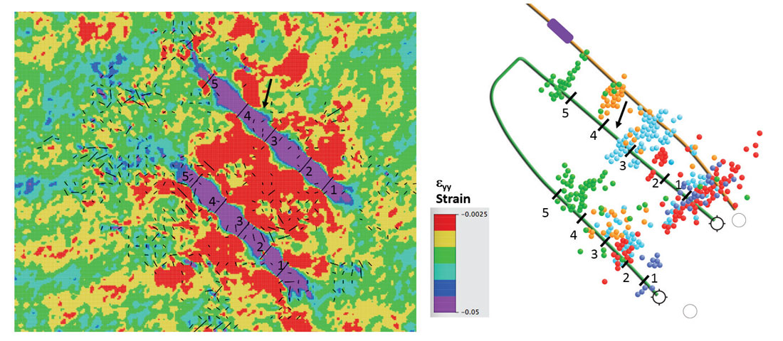
After completing the stimulation of well 2-7, pressure is added to well 7-7 to simulate its fracing in the new stress state created by the fracing of well 2-7. Figure 9 shows the resulting strain map that could be compared to the available microseismic events. The most important feature of these predictions is the ability to predict the fracing barrier between frac stages 3 and 4 of well 7-7 as shown in Figure 9. Another striking feature of these predictions is the good fracing North of stages 1 to 3 thus explaining the 75% contribution to the total production of these three frac stages. These predictions show an important overlap between the wells 2-7 and 7-7 that could be optimized by increasing the well spacing or reducing the pumping pressure. The optimization of well spacing or pumping pressure could translate into major savings for the shale operator and could be easily investigated quantitatively by using the MPM geomechanical workflow that can simulate multiple what-if scenarios as illustrated in Aimene et al. (2014).
Improved microseismic interpretation
The benefits of the MPM geomechanical workflow go beyond the prediction of microseismicity and could help understand other important results. Lee et al. (2014) recently published their findings on the use of an amplitude ratio method since they could not use a full moment tensor inversion due to the limited receiver coverage discussed in previous sections. The objective was to study failure mechanisms and to estimate the orientation of the natural fractures that are shearing and creating the microseismic events. The results of this work show the focal mechanism solutions pointing to a fracture orientation between 48 and 52 degrees (Figure 4). The actual fracture orientations seen from the interpreted image log at well 8-7 indicate the presence of natural fractures between 53 to 87 degrees. The results of the focal mechanisms and the predicted orientations seems to follow known geomechanical rules described below.
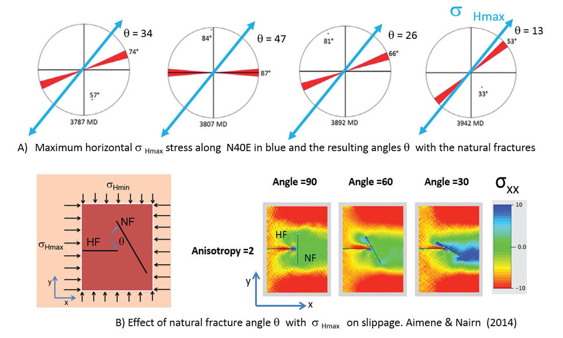
When a hydraulic fracture (HF) is propagating, its interaction with the natural fractures (NF) depends mainly on the anisotropy and the angle theta between the HF and NF. The MPM geomechanical workflow was used to better understand this interaction as the anisotropy and angle theta varies. Figure 10 shows a previously published numerical experiment conducted with the MPM geomechanical workflow (Aimene and Nairn, 2014). When considering the anisotropy case of 2 (close to the study area anisotropy of 1.8), one can notice that for an angle theta of 90 or 60 degrees, the remote effect of the hydraulic fracture on the natural fractures is minimal. When the angle theta reaches 30 degrees, one can see the beginning of conditions that could create slippage and shearing. As the angle theta gets close but does not reach zero, more shearing is becoming possible and it is more likely that a microseismic event could be generated. For the Montney shale example, we note that the angle theta between the maximum horizontal stress and the natural fractures varies between 47 and 13 degrees (Figure 10). The focal mechanisms results shown in Lee et al. (2014) suggests that out of the four fracture orientations observed in the FMI log, the most likely one to shear and create microseismic events, is the one along the 53 degrees orientation that will have a low angle theta of 13 degrees. The fractures with these orientation probably represent the only critically stressed natural fractures that will be responsible for most of the recorded microseismic events. The other natural fractures may contribute quietly to the success of the stimulation but do not necessarily manifest themselves through microseismic. This is one of the major reasons behind the use of the new MPM geomechanical workflow that can take into account the contribution to the SRV of all the natural fractures and not only the noisy ones that express themselves with a microseismic event (if we are lucky to record the microseismic event by placing enough monitor wells around the stimulated wells).
Conclusions
The application of the MPM geomechanical workflow to a Montney shale example leads to many interesting results. The main result is that the Montney shale operator could use this type of MPM geomechanical results to undertake operational changes that could lead to major cost savings. For example the derived differential stress map could be used to design engineered completions by skipping or combining the stages that could lead to poor fracing and production. The examination of the resulting strain distribution available around all the wells included in the geomechanical simulation could be used to optimize the well spacing in a given pad or reduce the pumping pressure for existing wells in a pad.
For the specific study area, the main results show that the Shear Wave Velocity Anisotropy map seems to provide a good proxy for the distribution of the natural fracture density. When using the SWVA map in the CFM approach to create the Equivalent Fracture Model (EFM), the resulting fracture orientations seem to correlate well with the fracture orientations observed in the FMI log. When using this EFM model in the MPM geomechanical workflow to represent the distribution of the natural fractures and their interaction with the hydraulic fractures, multiple results are derived. Firstly, the differential stress appears to correlate well with microseismic events and production logs. Secondly, the predicted strain which could be considered a good proxy for microseismicity seems to reproduce many features of the actual but limited microseismic events. Finally, the microseismic focal mechanisms indicate that the natural fractures along the 53 degree orientation are most likely the only critically stressed fractures that respond to stimulation by creating shear events that can be recorded by the currently available instruments designed for microseismic surveys.

Acknowledgements
The authors would like to thank Lee Hunt and Ayon Dey for their editorial comments and great suggestions. The authors thank Go Geoengineering (GoGeo) for providing the Equivalent Fracture Models (EFM) derived in FracPredictor™.


Join the Conversation
Interested in starting, or contributing to a conversation about an article or issue of the RECORDER? Join our CSEG LinkedIn Group.
Share This Article