Summary
Water supply in rural regions of southern Africa is complicated by the highly irregular nature of aquifers in weathered crystalline bedrock. Drilling success can be as low as 30%. Improvements in the success rate can be achieved by using simple geophysical investigations to target the thickest zones of weathering. More sophisticated geophysical surveys that image the full range in aquifer types can improve the success rate to 70%. In Malawi, a German government-funded aid program sited a total of 250 boreholes using a combination of borehole geophysics, ground-based frequency-domain electromagnetics (EM34 and Max-Min), and electrical resistivity imaging. The project represents one of the most intense applications of geophysical surveys to rural water supply in deeply weathered crystalline basement terrains in southern Africa. These data have been combined with hydrogeological data, geological maps, and satellite and airphoto interpretations, and the results stored in a Geographical Information System. Four years after the field program, all of the targets have been drilled, and 85% of the boreholes have achieved the required yield of 720 litres/hour (l/hr). The end result of the program is an increase in the availability of water for the 105 villages in the district, dramatically improving the quality of life for over 60,000 people. The legacy of the project also includes a dataset of 388 line-km of EM, 22 line km of resistivity imaging data, 23 sets of borehole logs, and geology and chemistry from over 300 boreholes, providing a valuable training tool for future groundwater exploration projects.
Introduction
Groundwater exploration in Africa has a long history with many major initiatives producing important steps in reducing poverty on the continent. The large rural sector in southern Africa relies on groundwater for 90% of its water needs. In most parts of Zambia, Malawi, Mozambique and Zimbabwe, large diameter open wells hand dug into unconfined aquifers and ephemeral springs are the most common water points. These wells are susceptible to drought and contamination. Foreign aid programs focus on deeper engineered wells in attempts to increase the access of villagers to safe and convenient supplies of drinking water. A typical adult in Malawi uses fewer than 30 litres of water per day, compared to 150 litres in western countries. In poor regions of Malawi, water consumption is less than 10 litres/person/day, resulting in the widespread occurrence of cholera, dysentery and dehydration.
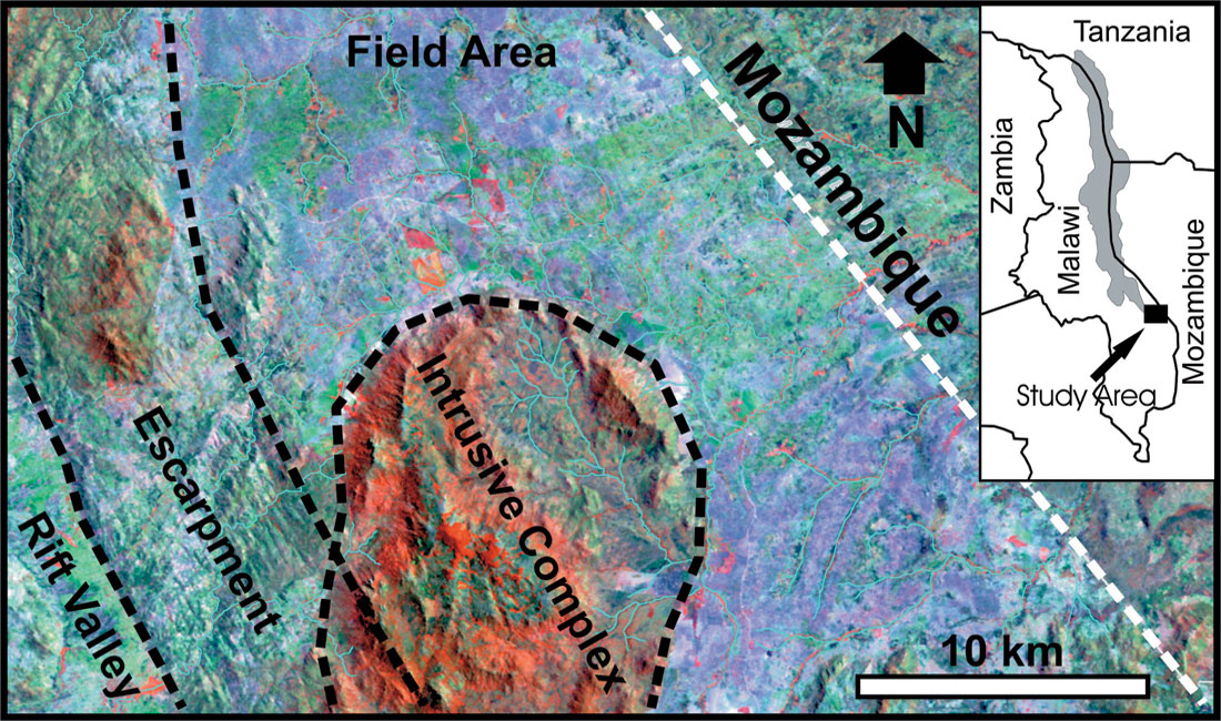
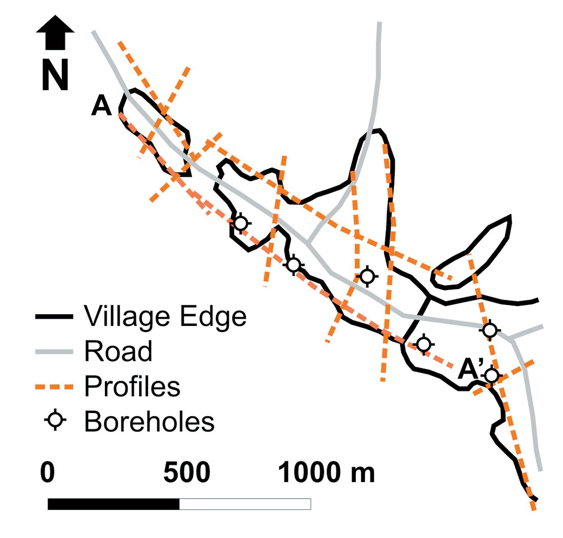
The East Mangochi Rural Water Supply Project is a major groundwater exploration program in Malawi, funded by the German government through the Kreditanstalt Für Wiedraufbau (KfW). The project is an extension of highly successful work completed by Gitec Consult GmbH in the African Rift Valley in southern Malawi. A total of 250 low yield boreholes (< 720 l/hr) are planned to supply 105 villages with potable water. The villages are located on the eastern edge of the rift valley (southern Malawi) within the Traditional Authority of Jalasi (Figure 1). The aim of the program is to provide one borehole for every 50 households. The boreholes must be located using a range of criteria, including hydrogeological setting, distance from the village (< 500 m), distance from latrines and cemeteries (> 50 m), and cultural factors such as family and village boundaries. This paper deals with the geophysical surveys used to map the aquifers and to template the physical properties of the hydrogeological setting.
Terrain, Geology, and Hydrogeology
Landsat TM imagery (Figure 1) and airphotographs were used to build a basemap of the region, comprising villages, roads and streams. A Geographical Information System was used to collate these data in a digital format. The bedrock geology was digitized from a set of 1:250,000 sheets (King and Dawson, 1976). The project area is underlain by typical Precambrian metamorphic rocks that have been subjected to tropical weathering and now form a regolith of between 5 and 50 m thickness. Outcropping bedrock is present in the field area, producing zones of very poor groundwater potential. The thickness of regolith is dependant on rock type, location of faults and fractures, topography and rainfall. The western edge of the study area is an escarpment elevated above the African Rift Valley (Figure 1). Major faults and fracture zones can be mapped using airphotographs and satellite images. Moving eastwards toward s the Mozambique border, the terrain is dominated by elongate depressions (dambos) and low ridges. Faults and fractures are difficult to map in these areas. The dambos are formed by the intense weathering of the rock, producing a thick soil horizon suitable for agriculture. In general, villages are located on the low ridges adjacent to the dambos and close to trails and roads. A major granitic complex outcrops in the centre of the field area (Figure 1). The area shown in Figure 1 as the intrusive complex is a forest reserve and is excluded from the study area.
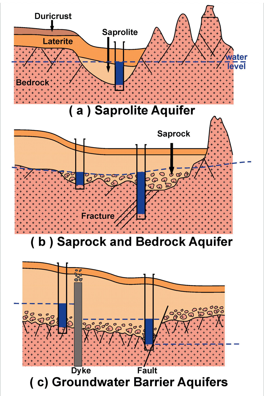
In deeply weathered terrains, the surficial geology can be divided into three units. The surface layer is a laterite or duricrust (Acworth, 1987). The next layer is a saprolite zone composed of the weathered products of the bedrock. The upper saprolite layer retains no characteristics of its original rock-type. The regolith grades into a less-weathered saprolite that preserves the fabric of the original rock type while displaying significant porosity as a result of weathering. At the base of the regolith a saprock layer forms on the top of the bedrock. Within the saprock layer, large blocks of unweathered bedrock are surrounded by a matrix of slightly weathered material (Wright, 1992).
Within the regolith and bedrock, four major aquifers can be found (Figure 2). The saprolite layer can be saturated, forming an aquifer with moderate porosity and high storativity but only moderate to low hydraulic conductivity (Figure 2a). The saprolite aquifer is usually confined. The deeper saprock layer may be significantly fractured but only has limited porosity. It has a low storage capacity but has high hydraulic conductivity through the connected fractures (Figure 2b). The narrow, sub-vertical fractured bedrock zones are difficult to hit when drilling. The ideal well will be cased in the duricrust to protect it from surface contamination. The well would be screened across the saprolite layer and into the saprock, taking advantage of high permeability fractures at depth, while drawing from the larger and m o re porous saprolite zone. Intrusive dykes and sealed faults can form barriers to groundwater flow, producing a suitable aquifer on the up-gradient side of the contact (Figure 2c).
Geophysical surveys are important for mapping all four types of aquifer. The saprolite and saprock aquifer are often mapped by simply locating the thickest regolith. Projects in Zimbabwe concluded that, based on electrical resistivity soundings, a layer with a resistivity between 50 and 150 ohm.m and a thickness greater than 25 m is likely to yield water at a rate greater than 3600 l/hr (Jones, 1985; Martinelli, 1984). The fractured bedrock and barrier aquifers require more sophisticated geophysical surveys and interpretation.
Geophysical Borehole Logging
The project commenced with a hydrogeological investigation that surveyed 100 existing boreholes in the region and reviewed existing geological information (basement maps) to determine the most likely aquifers. Prior to the surface geophysical survey, 23 boreholes were logged using the Geonics EM39 logging system (Figure 3b). Geophysical logging has proven to be useful in groundwater investigations in other parts of southern Africa (Shedlock, 1990). Geophysical logs can be used to identify the degree of weathering of the subsurface, to investigate the differences between productive and dry boreholes and to derive physical rock properties for the interpretation of surface geophysical data (Table 1). Gamma, induction and magnetic susceptibility logs were collected in the PVC cased boreholes (Figure 3a). The boreholes ranged from 15 to 50 m deep, and covered the entire suite of bedrock types, borehole yields and geomorphological settings.
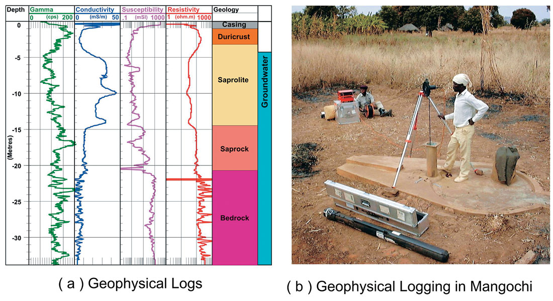
The gamma log is sensitive to the presence of naturally occurring radioactive elements such as uranium, potassium, and thorium. These elements are present in most geological formations in varying concentrations, depending on the lithology and mineralogy of the rock. In most Quaternary and Tertiary sedimentary sequences, clay rich zones produce strong gamma signatures. The duracrust at the top of the borehole shows characteristically high gamma counts (Figure 3a). However, in the saprolite layer, leaching of the radioactive elements may produce a decreased gamma count (Shedlock, 1990). In igneous bedrock, gamma counts can vary widely depending on the mineralogy. The saprock zone in Figure 3a shows a strong gamma response and the bedrock is variable but generally above 100 cps.
The Geonics EM39 induction probe measures the electrical conductivity of the formation. It is more suitable for water well surveys in Malawi than a resistivity log because most boreholes are cased with a PVC liner. Furthermore, an induction tool allows one to collect electrical data above the water table without any knowledge of the well construction details. In Figure 3a, the induction probe results are shown as both conductivity (mS/m on a linear scale) and resistivity (ohm.m on a logarithmic scale). The laterite and duricrust have a high resistivity due to the compaction and low moisture content. The saprolite has a lower resistivity suggesting it is saturated and has moderate porosity. The clay minerals will also be contributing to the low resistivity. The saprock has a high resistivity, reflecting the blocks of competent bedrock. Resistivities in igneous and metamorphic bedrock can exceed 5000 ohm.m. However, the induction tool is not sensitive to values greater than 1000 ohm.m. Steel casing in several boreholes prevented any resistivity data from being acquired.
The Geonics EM39 system also has a magnetic susceptibility probe that can be very useful in igneous terrains. The magnetic properties of a rock (susceptibility and remanence) largely depend on the concentration of magnetic minerals. The dominant sources of magnetism in rocks are ferromagnetic minerals such as magnetite, ilmenite and pyrhotite. In igneous and metamorphic rocks, ferromagnetic minerals are generally found as accessory minerals, with concentrations that vary from less than 1% to greater than 20%, resulting in a wide range of magnetic susceptibilities. In sedimentary rocks and weathered igneous and metamorphic rocks, magnetic minerals are usually oxidized and thus produce weaker magnetic responses. Typical susceptibility values for magnetically weak sediments and weathered bedrock are less than 0.1 mSI. Sediments and igneous rocks that contain minor amounts of magnetic minerals can have susceptibilities between 1 and 100 mSI. Unweathered igneous and metamorphic rocks containing abundant ferromagnetic minerals will have susceptibilities greater than 1000 mSI. Steel casing will mask the susceptibility of the surrounding rock. The susceptibility log (Figure 3a) shows the presence of unweathered blocks of igneous rock in the saprock horizon and clearly defines the top of competent bedrock.
Ground Geophysical Surveys
The surface geophysical program comprised a series of profiles (1 – 5 km long) through the centre and along the edges of each village (e.g. Figure 4). Three main geophysical tools were chosen for the program:
- A Geonics EM34 terrain conductivity system that yields estimates of the bulk conductivity of the regolith and bedrock for a coil separation of 10, 20 or 40 m and vertical or horizontal dipole configurations;
- An Apex MaxMin system that produces profiles of in-phase and quadrature responses at 4 frequencies (444, 888, 1777 and 3555 Hz) for a co-planar loop with spacings of 50 or 100 m;
- An Iris Syscal R2 electrical resistivity imaging system using 64 electrodes and a 5 m electrode spacing.
Electromagnetic Surveys
The first phase of the project involved a test of the two different electromagnetic systems (EM34 and MaxMin) on profiles through the wells with known geophysical structures. Based on the trials, the following configurations for the EM systems were adopted:
- EM34: 40 m coil separation, vertical and horizontal dipole, 20 or 25 m station interval;
- MaxMin: 100 m coil separation, all 4 frequencies, 25 m station interval.
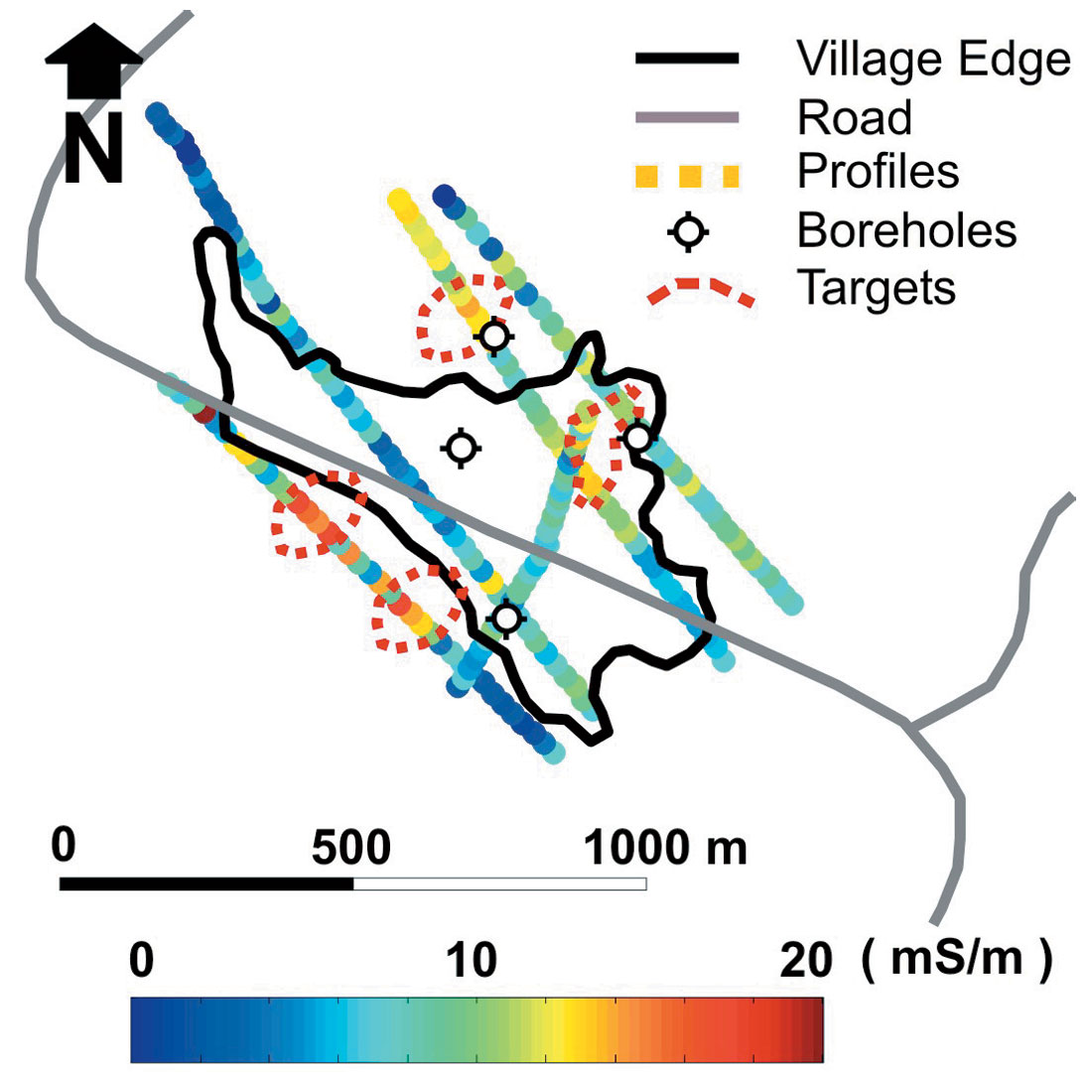
The conductivity of the near-surface and deeper layers could be determined from the response of the EM34 in horizontal and vertical dipole mode (McNeill, 1980). Figure 4 shows the apparent conductivity for the horizontal dipole mode (20 m depth of investigation) on the profiles through Malowa village. The background conductivity is low (< 5 mS/m) indicating very thin regolith. The anomalous zones greater than 15 mS/m have been identified as targets for drilling (Figure 4). Prospective areas beyond 500 m from the edge of the village are not considered suitable for the location of a borehole. Care was taken to identify sheet metal roofs, which are the main source of cultural noise in the villages. Based on the relative amplitudes of the vertical and horizontal component, it is possible to predict the thickness of regolith and the presence of any vertical conductors (faults and fractures). Figure 5a shows a profile from Sabili village, where the EM34 response is similar for both the vertical and horizontal dipole. This response is interpreted as a regolith with uniform conductivity that increases in thickness from less than 20 m on the flanks to greater than 40 m at station 1200.
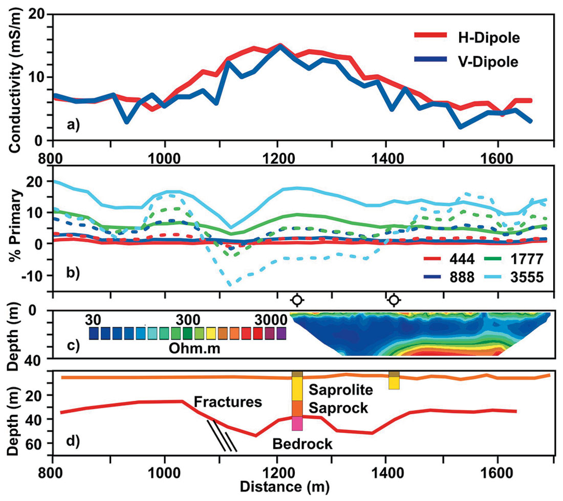
The MaxMin system provides a similar set of data but the addition of more frequencies increases the amount of quantitative interpretation (Palacky et al., 1981). With the coil spacing and the frequencies used, the MaxMin response is very different from the EM34 response (see Figure 5b). Qualitatively, the lower frequencies (444 and 888 Hz) are sensing deep into the bedrock; thus, amplitudes are low (< 5% of primary field). The higher frequencies (1777 and 3555 Hz) are sensing the regolith; thus, the amplitudes are high (> 15 %) and vary along the profile. Thick regolith (> 50 m) can be identified by large amplitude responses at all four frequencies. The anomaly at station 1100 m is a sub-vertical conductor, most likely a saturated fault or fracture zone. There may be several faults or fractures over the interval 1100 to 1400 that are deeply weathered, producing the MaxMin response.
In the interpretation of the profile (Figure 5d), the thick regolith between stations 1000 and 1400 provides a good location for siting a borehole. A significantly better yield may be expected from a borehole drilled into the fractures mapped at station 1100. The target at station 1225 was drilled and the results show a thin duricrust (6 m), saprolite to 25 m depth, a thick saprock layer (13 m) and bedrock at 38 m depth. The first water strike was at 9 m depth and the static water level rose to 4.4 m depth, indicating that the aquifer is confined. The hand pump has a potential sustained yield of 3600 l/hr.
Resistivity Surveys
Resistivity soundings have been used for decades in Africa to site boreholes (Caruthers and Smith, 1992). Resistivity profiling has also been used but the interpretation of the profiles is more qualitative than the soundings. The development of two-dimensional resistivity imaging in the last 10 years (Dahlin, 1996) offers an excellent combination of the sounding and profiling techniques. A 64-channel Iris resistivity system with a 5 m minimum electrode spacing was used on the project to provide high resolution images of the subsurface over targets identified by the EM surveys. The minimum electrode spacing of 5 m combined with a Wenner array produces a minimum depth of investigation of 1 – 2 m. A maximum current electrode separation of 360 m produces a maximum depth of investigation of 60 m. Surface resistivities were generally less than 100 ohm.m and contact resistances were low. On several lines a thick duricrust produced a surface resistivity of over 1000 ohm.m and water was needed to reduce the contact resistance. The multi-channel DC resistivity system collects many combinations of soundings along the length of the cable, for a range of electrode separations. The Wenner array was chosen for its high signal to noise ratio and vertical resolution. Dipole-dipole arrays may be more appropriate for imaging vertical structures. Two-dimensional inversion of the resistivity data (Loke and Barker, 1996) yielded excellent images of lateral and vertical resistivity changes that were interpreted as changes in the distribution of laterite, saprolite, saprock and bedrock (Figure 5c). Correlation with the borehole induction logs showed that the resistivity imaging system was capable of mapping the thickness of the duracrust and the saprolite layer to within 5% of its depth. The transition from saprock to unweathered bedrock is a more complex target and appears as a diffuse boundary between 500 and 3000 ohm.m in the inverted sections (Figure 5c).
Geophysical Inversion
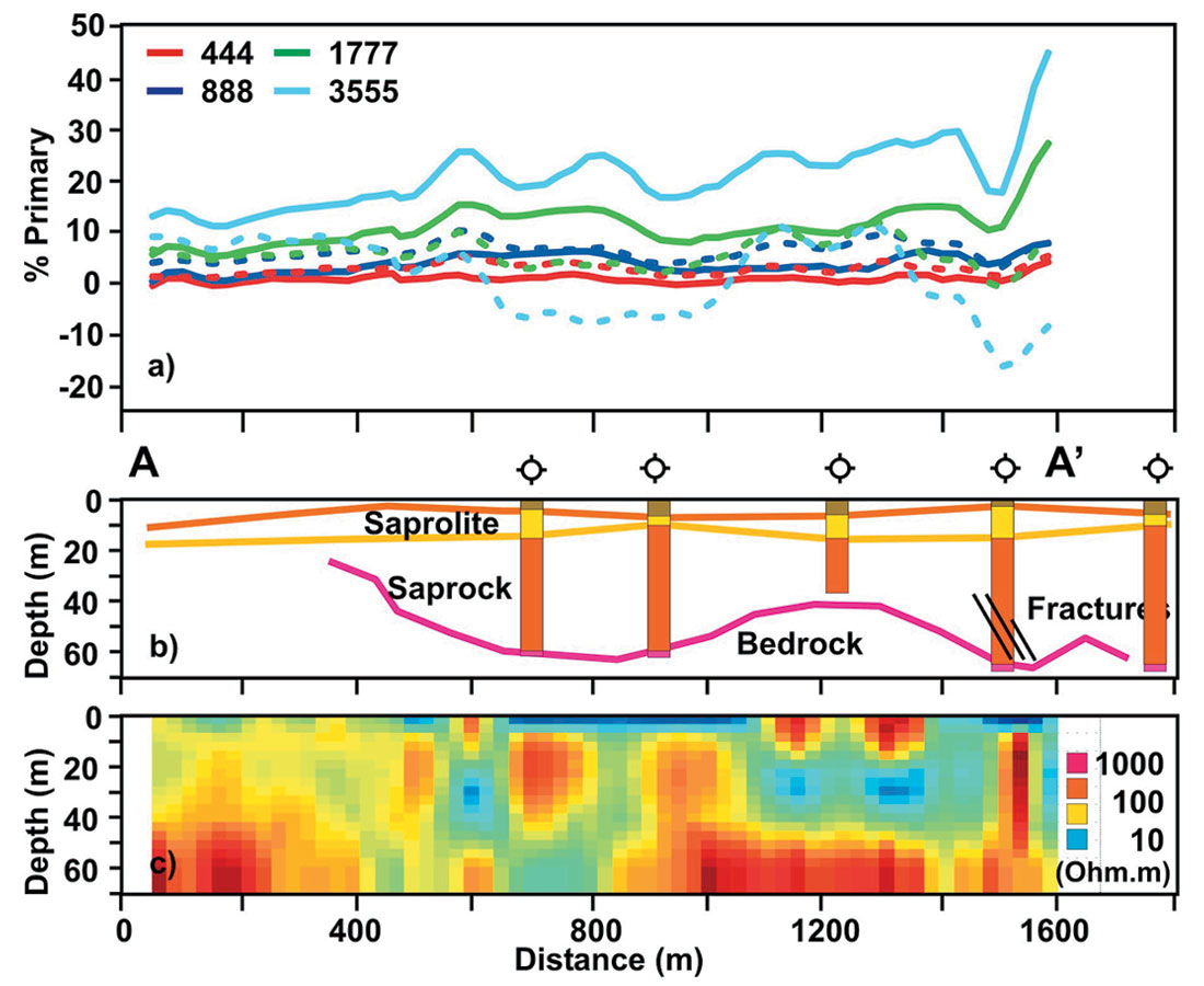
Most groundwater exploration projects have used very qualitative interpretations of the geophysical data to determine the presence of thick regolith or fractures. In this project we used several modern inversion routines to improve the quantitative interpretation. In particular, the MaxMin data are prone to ambiguous interpretations in regions of thick regolith and the inversion improves the ability to interpret depth to bedrock. Figure 6 shows the location of MaxMin profiles around the villages of Makalani, Kandulu and Simbili, located in the centre of the field area. The profile AA’ is shown in Figure 7. Based on the existing boreholes and the airphoto interpretation, the regolith was expected to be thick in this area. The MaxMin data were inverted using a one-dimensional inversion routine (Farquharson and Oldenburg, 2000) to yield an 8 layer model for the resistivity structure under each profile. The results of the inversion are still qualitative but the general trend of shallow bedrock under the western part of the line (stations 0 – 500 m) and thick, low-resistivity regolith between stations 500 and 900 is seen in Figure 7c. Over steeply dipping conductive faults and fractures (Station 1500), the 1D inversion of the MaxMin data is completely erroneous and these targets are best picked using the raw in-phase and quadrature curves. Four new boreholes were completed on this profile and they all encountered very weathered regolith and showed bedrock to be greater than 60 m deep. Groundwater depths increased from 3 m on the flanks to 15 m in the centre of the profile and potential yields varied from 1800 to 3600 l/hr.
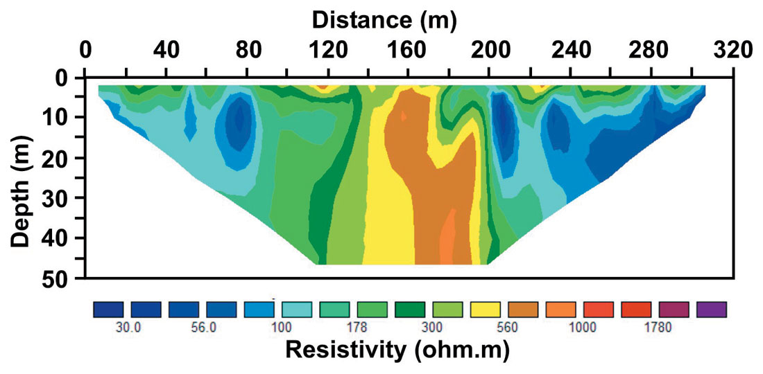
Inversion of resistivity data is commonly performed in all fields of exploration geophysics. In groundwater exploration, 1D inversion of soundings is rapidly being superceded by 2D inversion of complete sections. Rapid acquisition of resistivity cross-sections means that many more data points can be included in the inversions, improving the resolution of the technique. Two-dimensional inversion using a smooth inversion routine (deGroot-Hedlin and Constable, 1990) results in a model cross-section with diffuse boundaries between lithological units. In reality, resistivity boundaries may be very sharp and attempts have been made to produce a more “blocky” style of inversion. In general, the boundary between two units can be interpreted to occur at the inflection point on the smooth resistivity curve. Figure 8 shows a resistivity imaging section from Mtanga village. The vertical structure in the centre of the section is likely to be an igneous dyke. Lower resistivities on the right-hand side of the profile (topographically up-gradient) suggest that groundwater may be ponded against the dyke. Several similar “barrier” targets (see Figure 2) were mapped in the field area using the EM and airphoto interpretation.
Conclusion
This paper has shown the geophysical results from four villages with differing regolith and hydrogeological conditions. In the first example (Malowa village, Figure 4) the regolith is generally thin but several zones of deeper weathering have been mapped with the EM34 survey. Groundwater yield from the new borehole (3600 l/hr) is higher than for existing boreholes in the village. In the second example (Sabili village), localized thickening of the saprolite and a fault zone were mapped using a combination of EM and resistivity (Figure 5). A very thick blanket of saprolite and saprock was mapped around the village of Kandulu (Figure 7) and the four boreholes drilled had high groundwater yields. The final example is a groundwater barrier target that was imaged with the 2D resistivity system. The geophysical logs collected with the Geonics EM39 Borehole logging system provided very cheap and reliable estimates of the subsurface resistivity structure, allowing the surface geophysical data to be interpreted qualitatively. The resistivity sections produced by the 2D inversion of multi-channel surveys further improved the confidence in borehole siting. Given the size (large area and small budget) of most groundwater exploration projects in southern Africa, electromagnetic methods will continue to be the main geophysical exploration tool. Careful selection of acquisition parameters, processing steps and interpretation strategies are important for providing geophysical models that are useful for targeting successful boreholes. After, four years of community consultation, drilling and some additional geophysical surveys, the East Mangochi Rural Water Supply Project has attained a very impressive 85% success rate in the boreholes sited in Jalasi. Based on this project a more streamlined geophysical program is being considered for two additional phases of the project.

Acknowledgements
This survey was been undertaken with the support of the Government of Malawi, KfW (German Federal Restoration Bank), and Gitec Consult GmbH. Philip Hankin (Gitec Consult GmbH) is thanked for his support as team leader. The geophysical data were collected by Ansco Groundwater (Pty), Integrated Geophysical Surveys (Pty), and Komex International Ltd. Mapping and satellite imagery were supplied by the Survey Department of Malawi (Blantyre), and the Geological Survey Department of Malawi (Zomba). The logging system was kindly provided by Geonics Ltd. The inversion software for the EM data (EM1DFM) was supplied by the Geophysical Inversion Facility (UBC).


Join the Conversation
Interested in starting, or contributing to a conversation about an article or issue of the RECORDER? Join our CSEG LinkedIn Group.
Share This Article