Heavy oil or partially depleted conventional reservoirs typically require some form of stimulation to mobilize the oil. For more than a decade, steam injection programs in heavy oil reservoirs such as Cyclic Steam Stimulation, Huff and Puff, SAGD or some combination thereof have utilized microseismic monitoring to track steam movement within the reservoir, identify well casing failures, recognize potential caprock integrity issues, and characterize the activation of faults. More recently, source parameter investigations have identified stress transfer mechanisms associated with steam chamber development and out-of-zone growth. Microseismic monitoring has emerged as a valuable tool to infer reservoir behavior in response to production activities.
Increasing demand for secure sources of domestic energy and recent technological advances have driven dramatic growth in Canada’s oil sands. However, recent changes in oil prices have emphasized the ever present need to improve the economics of production, in particular, increasing recovery rates while reducing costs via improved operating efficiencies. Greater emphasis is also being placed on understanding long-term reservoir behavior. When integrated with existing methods such as logging, 3D seismic and engineering analyses, microseismic monitoring can provide a unique perspective on understanding of reservoir behaviour in response to stimulation as well as help operators optimize completion efficiencies and production performance.
Microseismic Monitoring: How it works
In response to the injection of steam into a reservoir during thermal Enhanced Oil Recovery (EOR), changes in stress conditions may induce rock failures similar to small micro-earthquakes. These failures generate seismic waves detectable by sensitive recording instrumentation positioned around the monitoring zone. Typically, induced seismicity is measured on a micro-scale at levels equivalent to very small earthquakes measuring from -3 to +1 on the moment magnitude scale. While microseismic monitoring of hydraulic fracturing is commonly performed using temporary wireline-based downhole sensor arrays, for EOR and long-term reservoir operations it is considerably more cost-effective to utilize a permanent Life-of-Field (LOF) approach to monitoring.
Microseismic sensor arrays for long-term reservoir monitoring consist of geophones or accelerometers. Depending on available infrastructure, multi-level sensor arrays are deployed in offset monitoring wells and/or on the surface. Combining permanent downhole arrays with near-surface networks ensures a broad spectrum of signals is accurately captured, ranging from small microseismic events to larger magnitude induced seismicity. The sensor arrays aim to provide adequate coverage of the zone of interest and may be deployed temporarily or permanently for periods ranging from a few weeks to several years. These sensors are deployed strategically to detect and locate the seismic activity associated with the reservoir’s response to the injection. Detected seismicity is continuously recorded and digitized by microseismic data acquisition units housed in protective units on the surface, and the microseismic data is relayed back to a central on-site location or MCC building where it can be processed in real-time.
Triangulation of microseismic event signals interprets the arrival times of compressional and shear waves (P- and S-waves) along with formation velocities to locate, visualize and interpret seismicity within the formation. Unlike traditional logging methods, the detection range and deployment options of passive seismic sensors provide an opportunity to see what is happening away from the wellbore. Real-time evaluation of microseismic activity above or within the caprock may identify a breach in the overlying rock layers or a leak in the well casing. Unusual clustering of microseismic events or the occurrence of larger magnitude induced seismicity (magnitudes above 0) may indicate the activation of a fault, prompting further investigation into the nature of the activation using advanced techniques. Microseismic data may also trigger alarms to notify operators to perform corrective actions to ensure the safety and integrity of storage operations. Figure 1 depicts microseismicity in a reservoir following injection activities, where each coloured sphere represents a single microseismic event.
Caprock Integrity and Out-of-Zone Growth
As pressure increases in a reservoir in response to steam injection, the reservoir can expand and deform, exerting stress on overlying caprock. Expansion of the formation can manifest as uplift at the surface. As the reservoir inflates, new micro-fractures may develop in the caprock or nearby faults and fracture networks may be reactivated. When this happens, seismicity associated with new fracture generation may be observed tracking upwards from the caprock boundary. In some cases however, seismicity may be observed as a result of stress changes in the reservoir. Seismicity above a caprock layer does not necessarily mean fluid communication. Microseismic methods, and advanced analysis in particular, are providing valuable insight into the underlying processes associated with out-of-zone growth and observed reservoir seismicity.
Many permanent microseismic monitoring arrays for long-term reservoir monitoring have been in operation for over a decade, and are found in regions such as the heavy oil sands of northern Alberta, the diatomaceous oil fields in California, and conventional oil fields in the Middle East. Recent advanced analysis of microseismic data associated with the injection of steam from two wells within an oil-bearing reservoir yielded some valuable insight into the processes associated with out-of-zone steam growth.
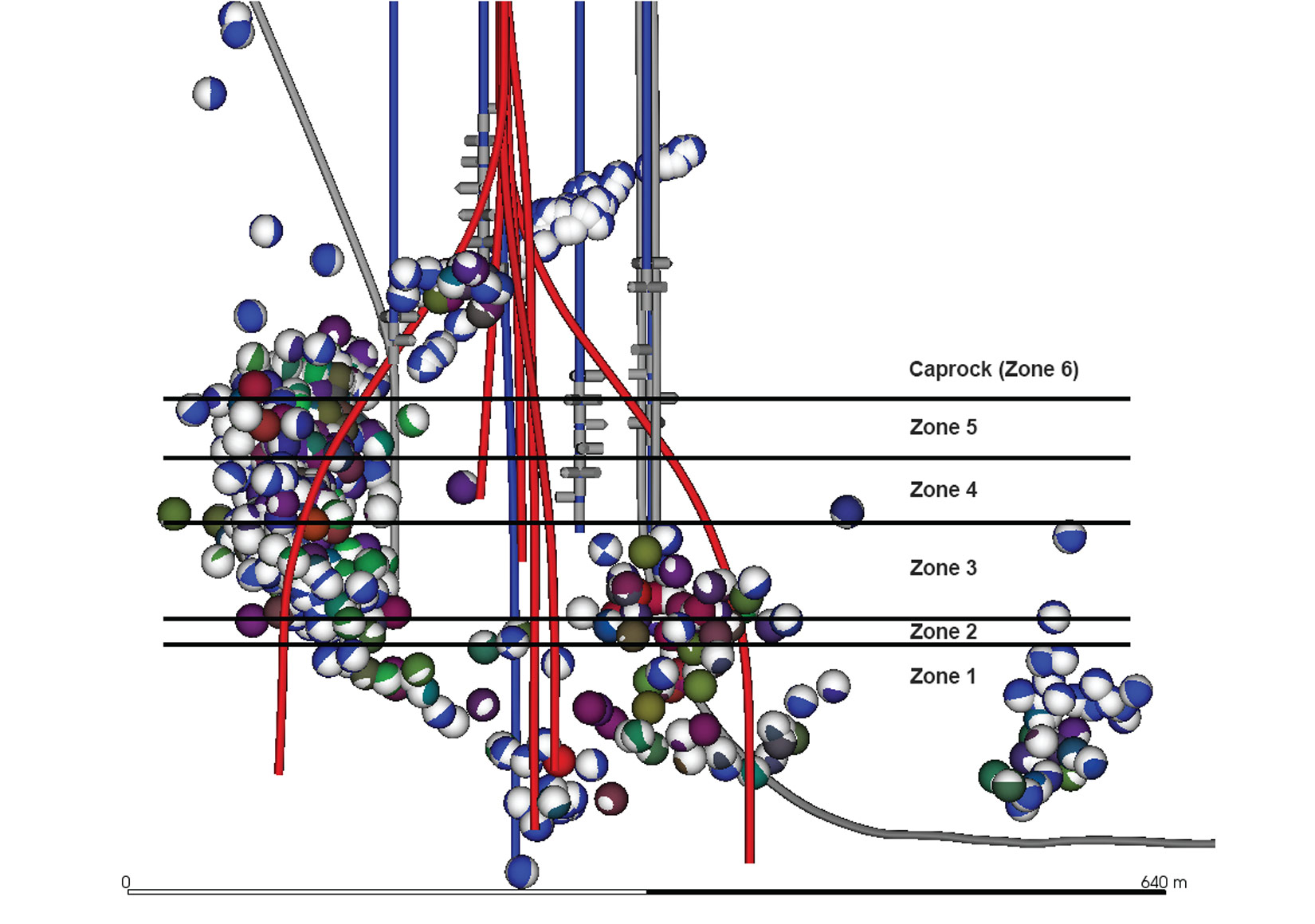
The reservoir under investigation was subdivided into 5 distinct zones, and was overlain by a formation which acts as the caprock for the reservoir (zone 6). The monitoring period encompassed an approximate two-month injection period, followed by the subsequent two-month soak cycle. During this time, a total of 824 microseismic events were recorded on multiple arrays and subsequently located, the majority of which took place during the soak cycle (Figure 2). In addition to utilizing first arrival data, the waveforms of individual events themselves contain information about the types of failure responsible for the observed signals. Seismic Moment Tensor Inversion (SMTI) analysis can be used to identify the modes of fracturing and evaluate any characteristic changes in stress-strain conditions between the upper and lower reservoir and the caprock.
SMTI analysis provides information about the mechanisms responsible for generating seismicity and interprets microseismic events as failures on fracture planes caused by slipping or shearing (double couple), tensile opening (mode 1 failures) or closures of previously open fractures. SMTI analysis involves projecting the seismic amplitudes and polarities (first motions) of the compressional and shear waveforms back to the event hypocenter to determine the failure mechanism responsible for generating the microseismic event. Interpretation of such mechanisms can determine temporal and spatial changes in the reservoir and define three-dimensional discrete fracture networks (DFN) that outline the size, orientation and complexity of fracture growth. Observation of failures with respect to pre-existing fracture and fault networks and the stress behaviour in the reservoir can indicate whether fractures are fluid-induced or due to stress-transfer effects.
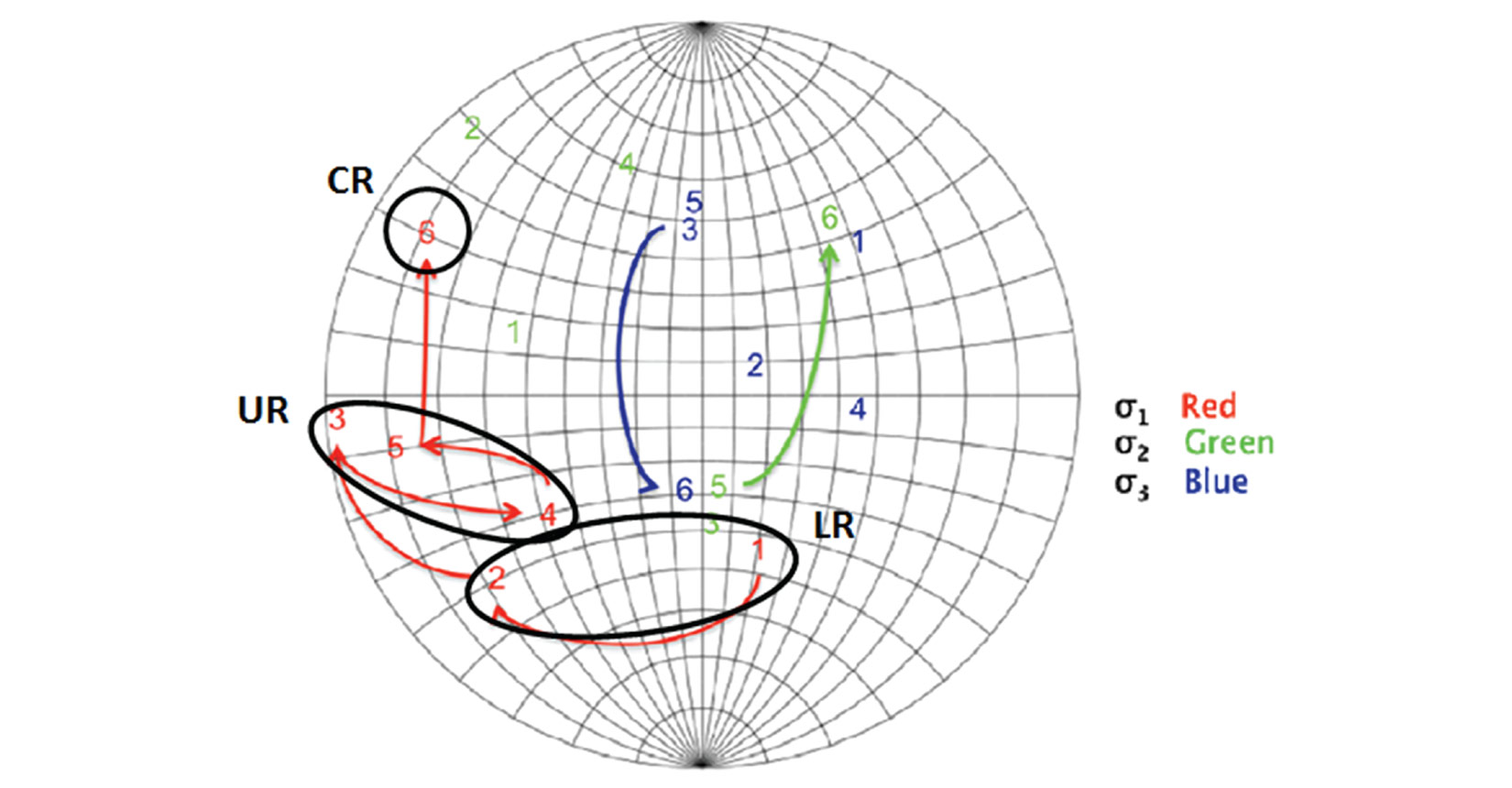
Microseismicity in the reservoir under investigation exhibited downward growth into the lower units (zones 1 and 2) as well as upward growth into the caprock (zone 6). Events within the reservoir appeared to be dominated by volumetric failures whereas within the caprock, shear-tensile failures with predominantly opening and closure events were identified. Numerous events for the out-of-zone growth regions appeared to follow planar trends, suggesting that the observed growth was related to the activation of larger geological structures. Using SMTI analysis, a progressive change in principal stress-strain axes was also observed in the reservoir with increasing depth. Average stress axes were calculated based on a Nearest Neighbor method as a function of depth interval utilizing a modified Gephart and Forsyth approach. The principal stress axes were mapped in terms of a stress path from the lower reservoir to the caprock. Figure 3 depicts a stereographic projection of the principal stress axes as they change in each zone. Following the maximum principal stress, three broadly defined stress behaviors were observed corresponding to the lower and upper reservoir zones, and the caprock, where the lower reservoir is represented by zones 1-2 and the upper reservoir is represented by zones 3-5. Based on these observations, it was proposed that the transition or rotation in principal stress-strain axes represented a change in the stress-strain magnitudes with depth and was responsible for the activation of pre-existing structures within the caprock. It was also observed that the majority of events occurred during the soak cycle rather than during active steam injection, suggesting that stress relaxation and stress transfer within the reservoir following steam injection was responsible for the seismic activity.
In this case, microseismic moment tensor analysis was used to identify the underlying processes associated with seismicity during steam injection. The analysis suggests that local variations in the stress-strain field due to steam injection can result in optimal orientations to allow for the activation of pre-existing faults, in this case located in the caprock.
Well Casing Integrity
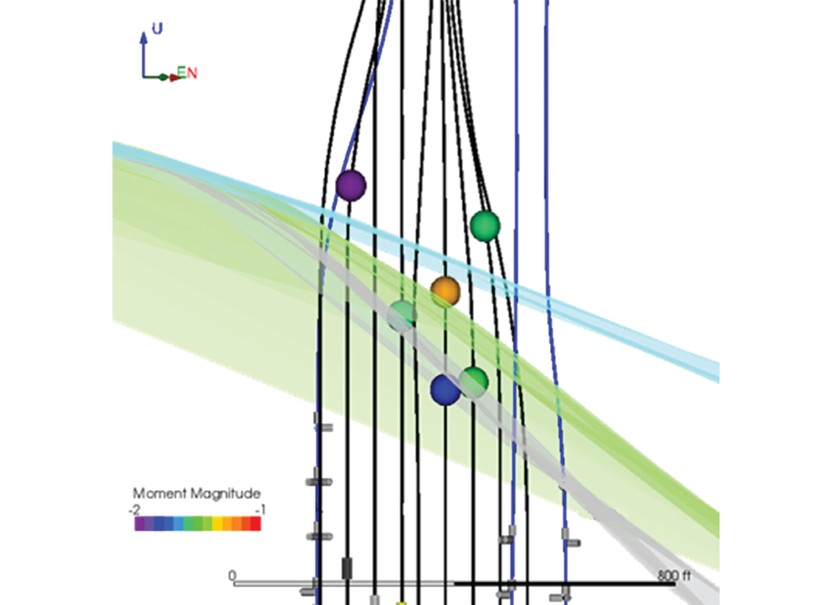
As a second consequence to the high temperatures and reservoir deformation during steam injection, well infrastructure may be subjected to harmful shear stresses, weakening the well casing or concrete and resulting in cement cracking or casing shear. Depending on its proximity to a microseismic recording array, a well casing failure may be detected as a larger magnitude seismic event close to the wellbore and above the injection zone. Casing failures also often exhibit distinctive signal characteristics such as higher P-wave amplitudes or certain P/S wave amplitude or energy ratios, coupled with observed changes in well pressures. During steam injection operations, six suspected casing failure events were detected as larger magnitude events above the target zone (Figure 4). Examination of the accompanying microseismic signal exhibited larger than normal P-waves consistent with tensile failure of the steel casing. In instances where multiple microseismic arrays are deployed in a reservoir, it may be possible to perform SMTI analysis on suspected casing failure events to examine the failure mode. In this example, three of the six suspected events exhibited tensile closure mechanisms, two of the events exhibited shearing mechanisms with a moderate compressional component, and one event exhibited a dilatational or explosive mechanism. All events aligned with an unconformity plane intersected by the well.
Steam Movement Imaging
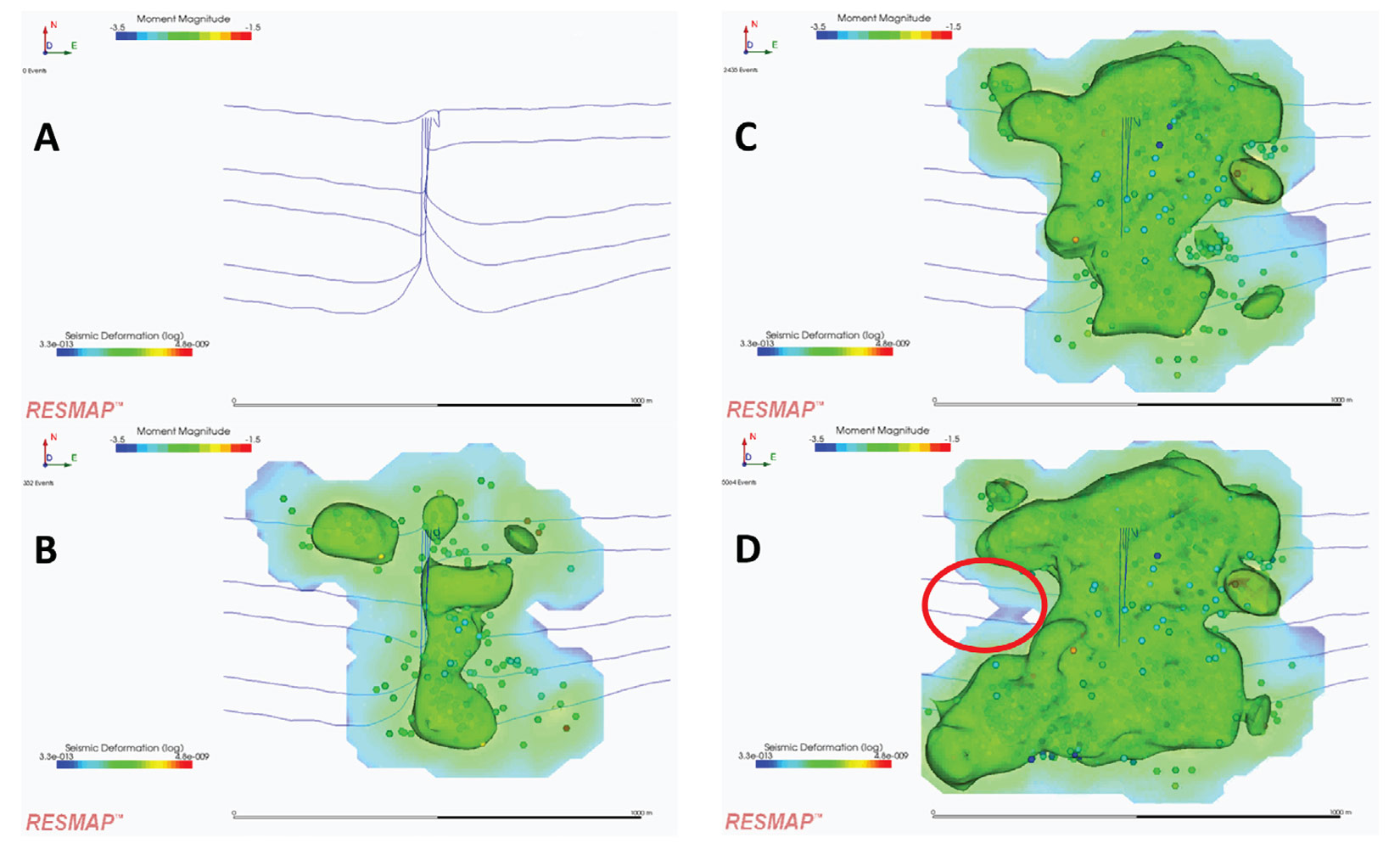
Depending on the injection pressures or formation properties, steam injected into oil reservoirs modifies the stresses in the reservoir and can induce tiny fractures along the edges of the steam front. Operators can benefit from the ability of microseismic monitoring to visualize the position and movements of a steam chamber within a reservoir, and learn how the steam is developing within the reservoir over time. For one particular steam injection project in North America, microseismic has been continuously monitored for more than ten years using a permanent downhole monitoring system installed on the north side of a well pad containing 10 horizontal treatment wells. Microseismic monitoring was used to track the steam front over time and determine the estimated steam chamber using seismic deformation. Figure 5 depicts the progression of steam chamber development from A, at the start of the project, to D, approximately 8 years later. In this case, the observation of a by-passed zone such as the area in the left-hand center region of image D was identified as an area to target with selected steaming cycles, to ensure maximum production.
Fault or Fracture Activation
In some formations, such as in South-Central California, large heavy oil bearing diatomite reservoirs have relatively low permeability and benefit from extensive hydraulic fracturing to increase permeability prior to steam injections. By using advanced geophysical analysis such as SMTI, microseismic events can be characterized, by failure type, allowing engineers and geophysicists to better understand how the reservoir rock is breaking. By understanding which fractures within the reservoir are shearing (non-opening) vs. isotropic (fractures that open up the rock mass and create volume related changes), producers can begin to better understand which areas of the stimulation are enhancing permeability and will therefore contribute positively to increased resource production.
In one such diatomite formation, continuous microseismic monitoring was performed for injection and production stages of a ‘Huff and Puff’ operation. Following hydraulic fracturing, steam injection helps to reduce the viscosity of the oil and creates a large, contained zone of increased temperature and pressure. The resulting reservoir deformation releases detectable seismic energy. Microseismic events were recorded using three permanently installed high-temperature downhole monitoring arrays deployed in three vertical observation wells around the treatment zone.
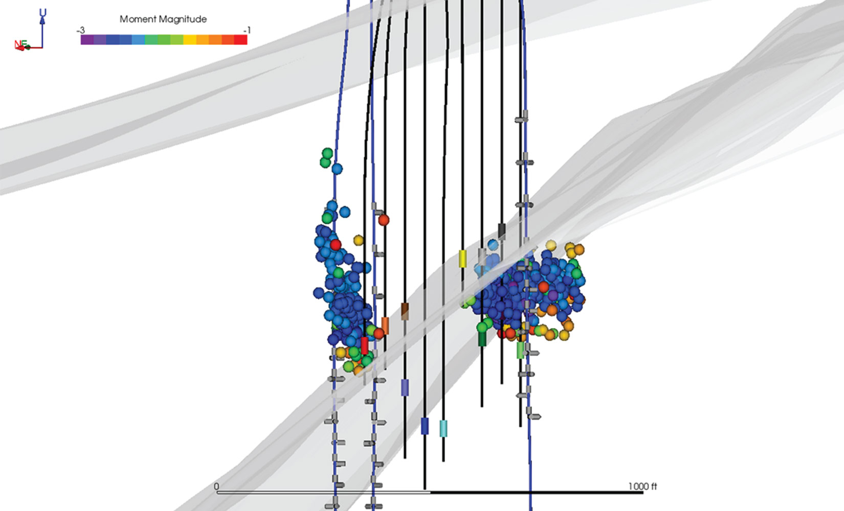
During steaming operations, two unique clusters of seismicity (Figure 1) were observed in the reservoir; the first (Cluster A, cluster on the left in Figure 1) was observed during the production cycle of one well and exhibited unconstrained vertical movement while the second (Cluster B, cluster on the right in Figure 1) was observed during the production cycle of a neighbouring well. Advanced SMTI analysis was used to further examine the specific failure mechanisms associated with each cluster.
A helpful way to display the results of SMTI analysis is with a source-type diagram or Hudson plot (Figure 6). This diamond-shaped plot depicts several types of failure mechanisms in various quadrants of the plot: double couple (DC) or pure shear mechanisms will cluster in the centre; isotropic or pure opening or closing events will be positioned at the top or bottom of the figure, respectively; and finally tensile opening and closing failures can be found on the upper-left and lower-right of the diagram.
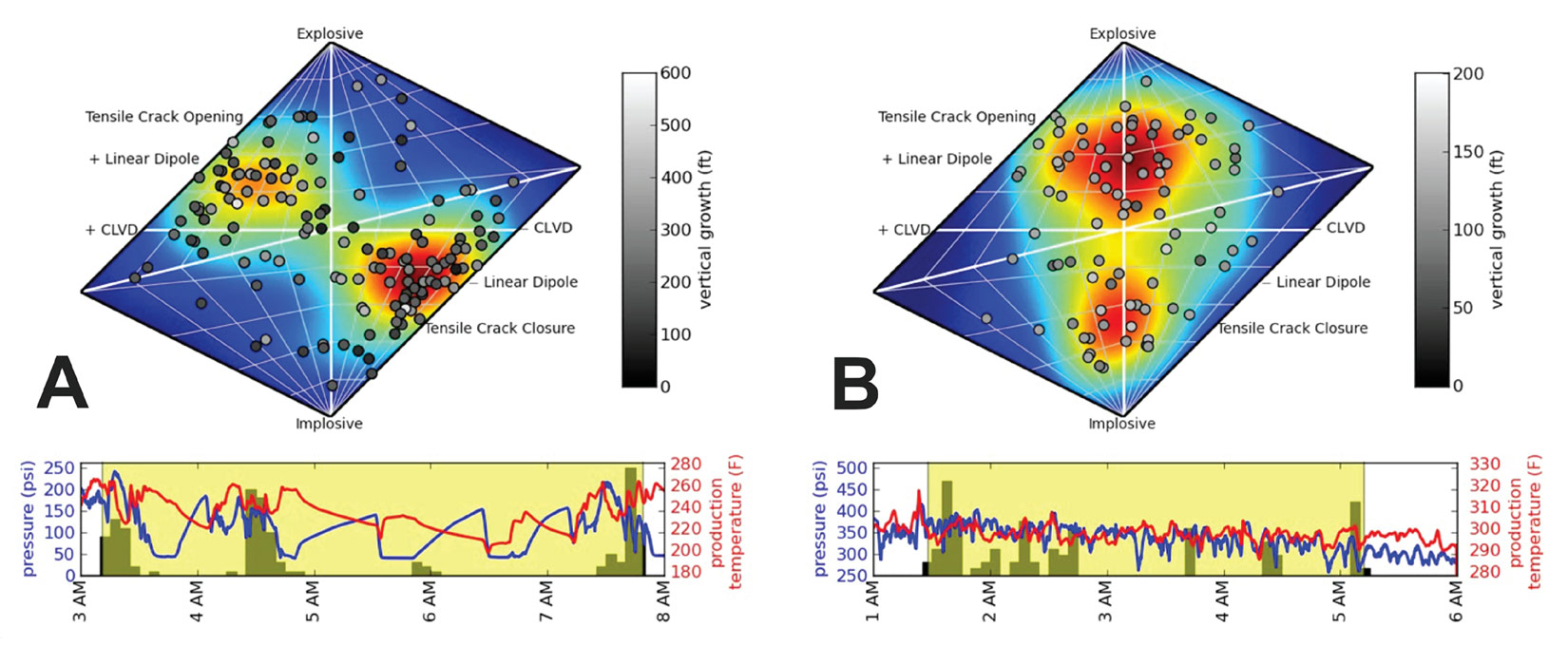
A – events depicted in cluster A for uncontained fracture growth;
B – events depicted in cluster B for contained fracture growth. The events, colored in gray scale according to vertical growth, overlay a density plot for the distribution.
The source-type plot for Cluster A (Figure 6A) indicated that the events were primarily shearing and tensile opening/closing events. This pattern is similar to observations of fracture propagation in hydraulic fracture stimulations, where opening events dominate early in the treatment and extend outwards into the formation, followed by closing fractures nearer to the wellbore. An interpretation of the observed mechanisms is that a fluid traveled through a pre-existing vertically oriented fault or fracture. By following this path of least resistance, the fluid propagated upwards in an uncontrolled manner.
For Cluster B, the source-type plot (Figure 6B) indicated that the failure mechanisms were primarily explosive and implosive in nature, coupled with pure shearing. This pattern is very typical of how steam chambers develop, and may be related to the inflation and deflation of the production zone as steam interacts with the pore spaces of the diatomite. The microseismic activity associated with Cluster B was well contained and represented optimal steam chamber development.
As cost reduction and completion efficiency become ever more critical, operators require methods to help them achieve production goals in unconventional reservoirs. The use of microseismic monitoring in heavy oil applications has been quietly evolving over the past 10 years. As microseismic monitoring continues to develop, its versatility will continue to support new and different applications aimed at providing operators with tools to optimize production. Future developments in microseismics will continue to focus on integration of advanced microseismic information with geophysical, geological, engineering and geomechanical data to gain a further understanding of reservoir behaviour.


Join the Conversation
Interested in starting, or contributing to a conversation about an article or issue of the RECORDER? Join our CSEG LinkedIn Group.
Share This Article