Much geophysical research [3] focuses on improving the quality of time imaging by aligning the reflectors based on CMP seismic gathers. Various formulas for moveout correction that consider real data complexity and accordingly, the non-hyperbolic character of a traveltime curve, have been proposed. Researchers attempt to avoid nonlinear stretch on short time intervals and distortions caused by a significant curvature of reflecting boundaries. Traditional methods suffer from two major shortcomings. They either require information about additional parameters like anisotropy, or the algorithms applied for correction are not particularly effective.
A new method of moveout correction and seismic data stacking, called Multifocusing, has been developed [1]. Conventional imaging techniques (CMP stack, DMO, time and depth migration) require varying degrees of accuracy of the section’s velocity model. Unlike them, Multifocusing is practically free of this limitation, using no other information about the macro-velocity model than its near-surface velocity.
Multifocusing is based on the patented theory of homeomorphic imaging, developed by Gelchinsky et al. [1, 4] In the Multifocusing approach, each zero-offset trace is constructed by stacking traces that need not belong to the same CMP gather; but rather, whose sources and receivers are within the limits of a specific super-base in the vicinity of the central point X0. The size of the super-base is determined by the size of the Fresnel zone. All traces entered in the super-base and there may be thousands of such traces, are called super-gather.
This new concept has led to the development of a new general approach to moveout correction. According to this approach, the NMO correction depends not only on one parameter – velocity – but on three wavefront parameters: β0 — the angle of the wavefront emergence to the central point of the super-gather, whose size is controlled by the first Fresnel zone; and the curvature radii (Rcre and Rcee) of two fundamental wavefronts. The first wavefront (CRE) is formed by a source located where the zero-offset ray emitted from the central point hits the reflector. The second wavefront (CEE) is formed by normal rays emitted by different points on the reflector (as in an ‘’exploding reflector’’ scenario).
Let us consider a normal ray that starts at point X0 (referred to as the central point) with the angle β0 to the vertical line (Figure 1).
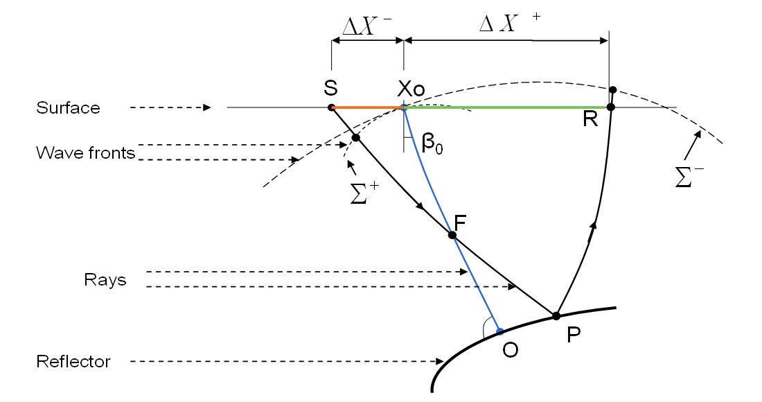
The ray hits the reflector at point O and returns back to X0. A paraxial ray from the randomly located source S intersects the central ray at point F, arriving back to the surface at point R of the receiver. The moveout correction [1-3] for the arbitrary source and receiver offsets in the vicinity of the normal ray is described in the following equations:
where
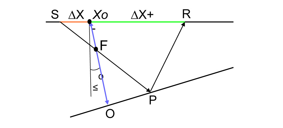
Here ΔX+ and ΔX- represent a distance from the source and receiver to the central point of the super-gather, respectively; RS and Rr are the radii of the fictitious wavefronts Σ+ and Σ- near source and receiver respectively; V0– the wave velocity near the surface; σ – the focusing parameter. This parameter, in the case of plane and sloping reflector (Figure 2) and constant velocity, is equal to the relationship between two distances: the distance OF (focusing point F and point O where the normal ray hits the reflector) and distance OXo (point O and the central point Xo). Thus, the focusing parameter is defined as σ = OF / OXo.
In the case of a curvilinear reflector and variable velocity, the focusing parameter is calculated using Multifocusing Equation (3). As seen in Equation (1), the time arrival curve in Multifocusing is not hyperbolic. As shown in experiments on synthetic models, Equation (1) closely approximates reflected wave arrivals on large offsets.
Implementation of the Multifocusing method is based on a phase correlation of the signal on the observed seismic traces included in the super-gather. The data for the specific t0 are moveout corrected along different traveltime curves, to find the curve closest to the traveltime curve of the signal. The unknown parameters β0, Rcre, Rcee are estimated using a procedure that consists of finding a set of parameters that maximizes the semblance function calculated for all seismic traces in the super-gather, in a time window along the traveltime curve defined by the Multifocusing moveout correction (Equation 1). The semblance is maximized using a nonlinear global optimization method. The automatic procedure looks for the set of parameters that maximizes the coherence criterion, calculated for all seismic traces in the vicinity of the central point. Parameter Rcre is connected with VRMS by the formula Vcre = V2RMSt0 / 2V0, where t0 is a zerotime on the central trace. Parameter Rcee depends on curvature of reflector. It is equal to ∞ for a plane reflector. For diffracted waves Rcee equals Rcre.
A summation along the trajectories corresponding to an optimal combination of wavefront parameters enables the calculation of a Multifocusing stack (MFS) without stretching the signals. The Multifocusing moveout correction for a given sample of the image trace at t0 depends on the incidence angle and on curvatures measured on seismograms, and does not involve the value of t0 itself, as in the CMP method. All the samples from a given reflection event on a given central trace will have the same parameters within the duration of the wavelet; hence, the moveout correction will be constant along the wavelet.
Thus, Multifocusing has the following main advantages:
- A higher SNR due to the summation of a greater number of traces.
- Stretch- free stacking due to independence of moveout corrections from the time parameter t0 .
- Non-hyperbolic moveout corrections.
These advantages have led to higher-quality data processing of multi-fold data acquired in complex geological conditions. The imaging of reflections in the upper part of the subsurface is now more reliable. This also provides an opportunity to increase the signal-to-noise ratio for old seismic data acquired with a small fold.
The case study below illustrates the effectiveness of the new method using data acquired in complex seismo-geological conditions, where seismic energy is scattered and curvilinear reflectors are observed. The first example illustrates the efficiency of Multifocusing in its “pure” state (without post-stack migration); the second is a migrated stack. Note that identical pre-processing was applied in both methods.
The first example (Figure 3a) shows the data processed using the CMP method. The data consists of 240 shot gathers with 40 meters source spacing. The average number of traces per CMP is 75. The geology of the region is characterized by complex tectonics. A billowy relief and complex subsurface conditions, in addition to a geologically complex structure, result in a very noisy seismic wavefield. One may see that standard CMP processing, including detailed velocity analysis, has not resulted in reflections which are sufficient for geological interpretation.
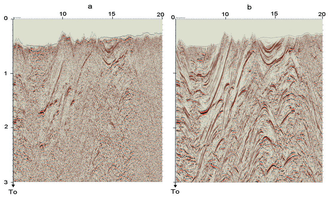
Figure 3b shows the MFS for the same data. All the sections are much more detailed than the sections processed using the conventional method. These improvements are due not only to the statistical effect of the super-gather summation, but mainly due to the optimization of parameter Rcee which is connected to the reflector curvature.
The second example (Figure 4a) shows the data processed using a traditional CMP method with post-stack Kirchhoff migration in the final stage. The data consists of 280 shot gathers with 50 meters source spacing. The average number of traces per CMP is 70. The geology of the region is very complex.
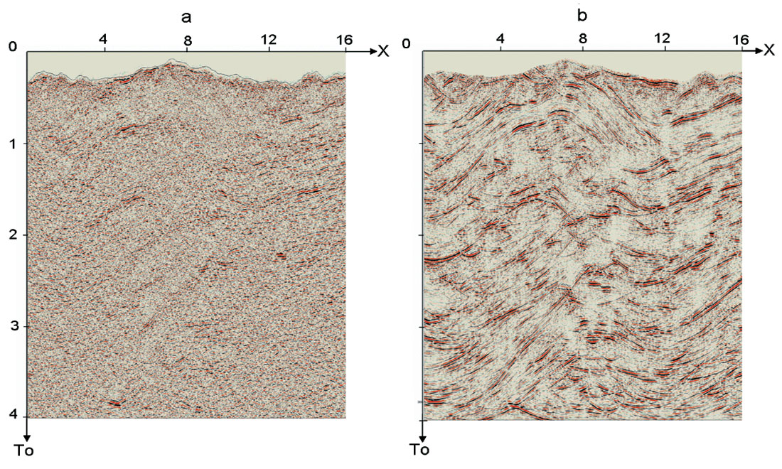
Mapping and high-quality interpretation were impossible due to the complex relief and the absence of extended reflections.
Figure 3b illustrates the MFS with subsequent migration for the same data. The improved results using the new application are obvious: the shallow and deep events are well defined. The reflections, although not extended, are defined by the new method and enable estimation of the geological structures, leading to reliable geological interpretation.
Conclusion
A new method of seismic data processing has been developed. The method consists of stacking seismic data with arbitrary source-receiver distribution according to a new moveout correction formula. The time moveout parameters of Multifocusing are the emergence angle of the normal ray and the wavefront curvatures for two fundamental wavefronts. The traveltime curve of the new method provides a better approximation of the actual reflection traveltime then the standard hyperbolic curve. The method is not dependent on the geological section model and consists of stacking seismic data with arbitrary source-receiver distribution near the central points. A higher SNR, due to the summation of a greater number of traces and the absence of stretch effect, delivers a significant increase in the signal-to-noise ratio for both deep and shallow reflections.


Join the Conversation
Interested in starting, or contributing to a conversation about an article or issue of the RECORDER? Join our CSEG LinkedIn Group.
Share This Article