Summary
In depth imaging, after the Kirchhoff method, wave equation techniques have been used most widely in the industry, especially in subsalt imaging. Traditional wave equation migrations use one-way downward continuation and this is why turning ray is not incorporated into these algorithms. Therefore, in order to image the salt face, Kirchhoff migration is performed instead of the wave equation method. The reverse time migration combines both benefits of one-way wave equation migration for the multi-arrivals and Kirchhoff migration for steep and overturned reflectors. The other advantage of the reverse time migration is the amplitude handling compared to the previously mentioned methods. It provides correct amplitude and phase information at reflectors.
Introduction
Reverse time migration has been around for a long time, but due to the runtime constraints it had not been feasible to run in prestack mode until a few years ago. Reverse time migration was originally developed for stack sections (Whitmore, 1983; McMechan, 1983; Baysal et al., 1983; Loewenthal and Mufti, 1983; Levin, 1984). It has been implemented in the prestack domain for both acoustic (Chang and McMechan, 1986; Etgen, 1986) and elastic (Sun and McMechan, 1986) media. Recent works show the runtime can be reduced by orders of magnitude if the implementation is performed in the frequency domain instead of the time domain (Plessix and Mulder, 2002). The finite-difference method used with the full two-way wave equation can model all wave phenomena and provide correct amplitude information for reflectors.
General description of the two-way wave-equation method
Reverse time migration is more general than any wave equation migration using downward continuation by allowing the wave to propagate both ways. The shot-profile pre-stack reverse time migration can be described as follows:
The first step of the process is to forward propagate a shot wavefield from the shot point to out past all the reflecting horizons of interest using equation (1). The next step is to propagate the recorded wavefield backward to the positions of the reflectors using the same equation (1).

At each time step where the shot wavefield and the recorded wavefield overlap are the places for reflecting interfaces. Finally the zero-lag value of cross-correlation of the two wavefields is taken to obtain the positions of the reflectors.
The imaging condition for pre-stack reverse time migration can be expressed as:
This imaging condition produces offset domain common image gathers (CIGs), which are easily transformed to the reflection angle domain CIGs (Rickett and Sava, 2001) resulting in an essential input for velocity updating.
Reverse time migration, since this process employs forward modeling using full wave equation, has an additional benefit of convenient verification of the velocity model.
Velocity model building using two-way wave-equation migration
Model building is an essential part of depth imaging where several tools are used in order to achieve the best possible velocities. In the Gulf of Mexico environment there are significant steps required. The supra salt velocity field could be derived in several ways using Kirchhoff or wave equation output (reflection offset or angle gathers) through vertical updates or ray trace tomography. In this step reverse time migration might be an expensive algorithm to use.
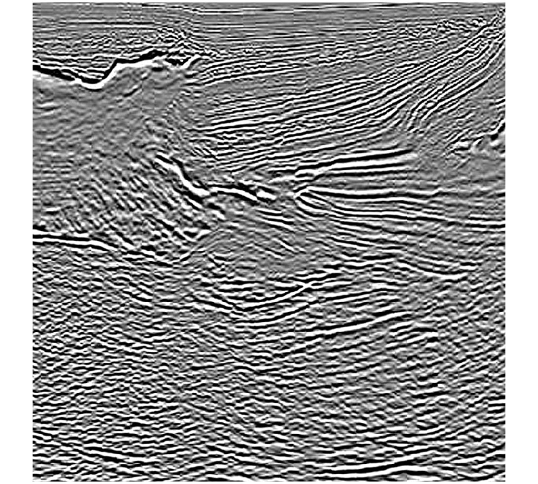
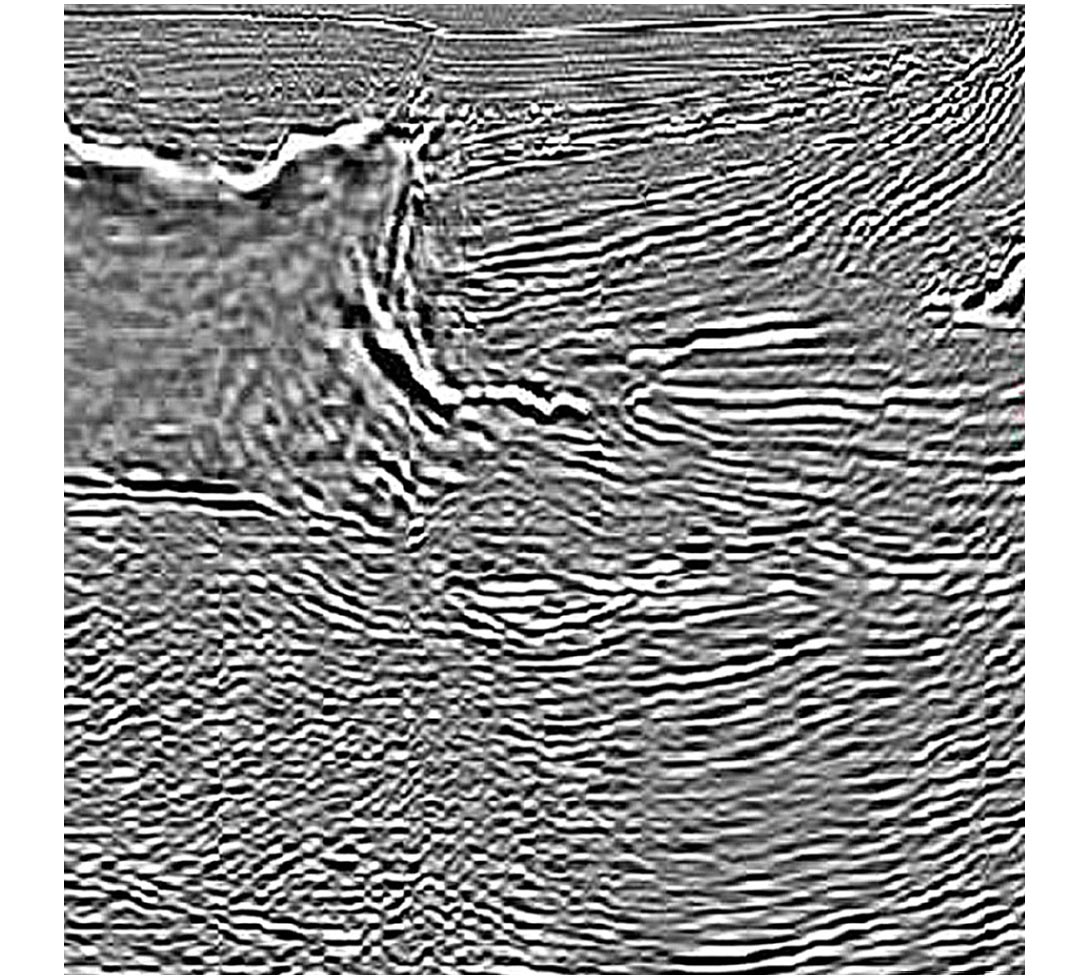
Salt geometry determination is one of the most critical steps towards the final outcome. This phase of the model building involves migration techniques which go beyond 90 degrees, the most convenient being Kirchhoff summation. Reverse time migration has the benefit of accurately imaging salt flanks (see figure 1a and 1b), being multi-arrival, and capable of producing models to aid, validate, and interpret the velocity model. Modeling raises questions at every stage of the construction which requires convincing answers.
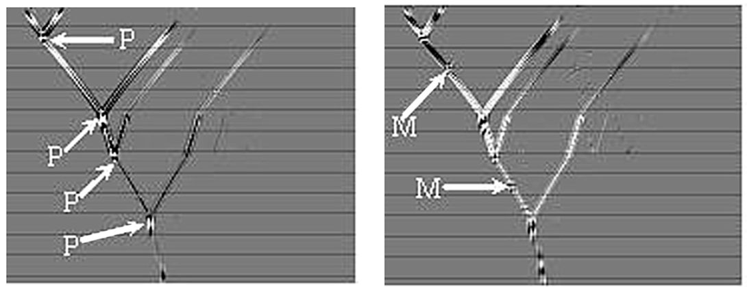
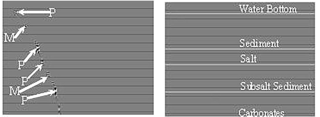
Model Validation includes finalizing salt geometry through analysis of the created image with the semi-final velocity model and modeling capability in reverse time migration to confirm whether images are created by primary energy or some other wavefield components producing false images. During the migration X-T planes can be extracted at image points with minimal effort distinguishing between multiple and primary events. If an event is a primary then at reflection position the downward and upcoming wavefield meet (see figure 2a). If an event is multiple there is a downgoing wavefield only (see figure 2b). If the one-way wave equation technique is the tool used for the imaging the X-T plane is simple but less conclusive. Since reflections are not part of the one-way wave phenomena there are no clear indications where the primaries and multiples are (see figure 2c). Only the synthetic model itself (see figure 2d) can be used to identify primaries and multiples on the one-way X-T snapshot.
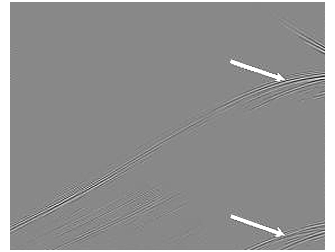
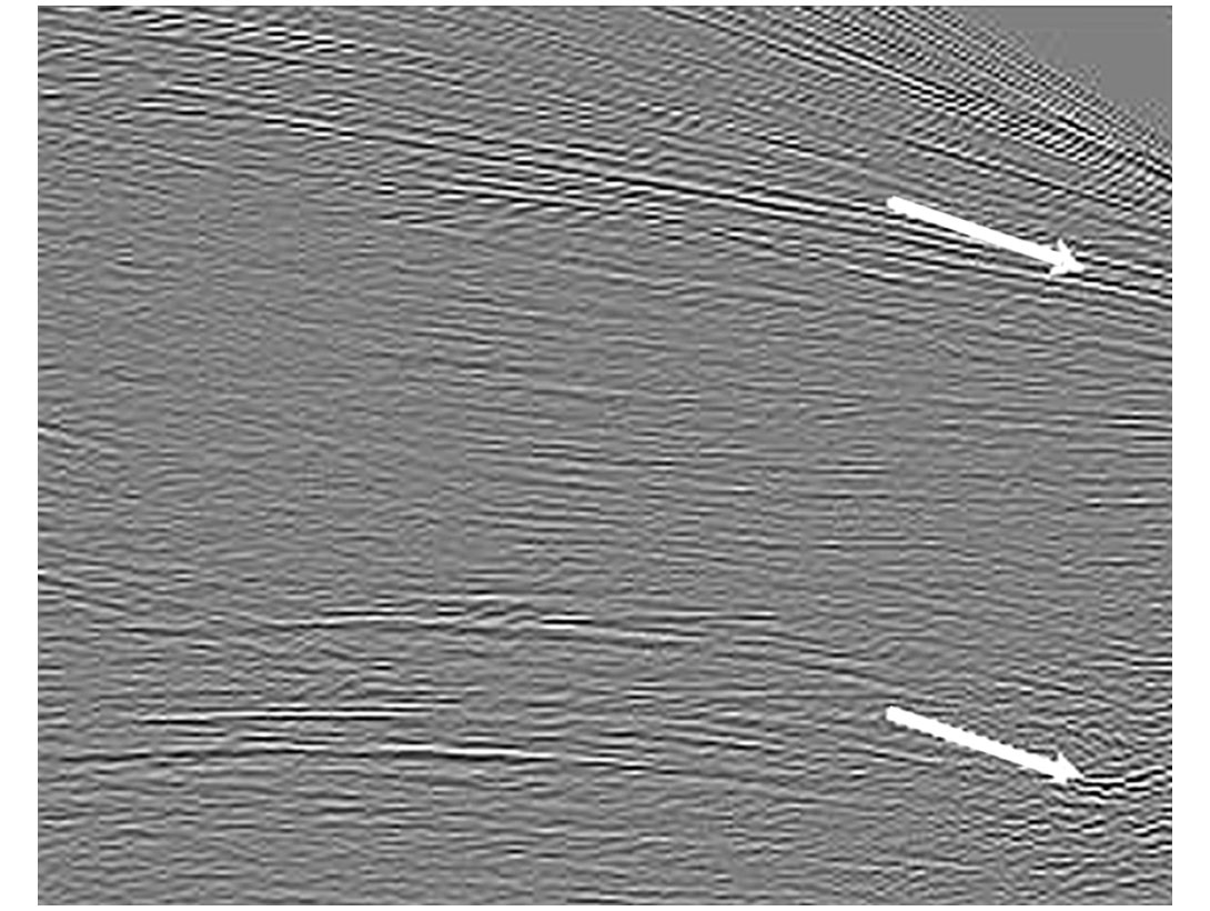
The forward modeling capability of the reverse time migration is a perfect tool for this step. Alternatively, it can lead to a different velocity updating technique called waveform tomography, which would allow us to derive models through comparing forward modeled shots to real acquired data. In order to identify turning rays critical for steep salt flanks, model shots can be compared to real data for verification (see figures 3a & 3b).
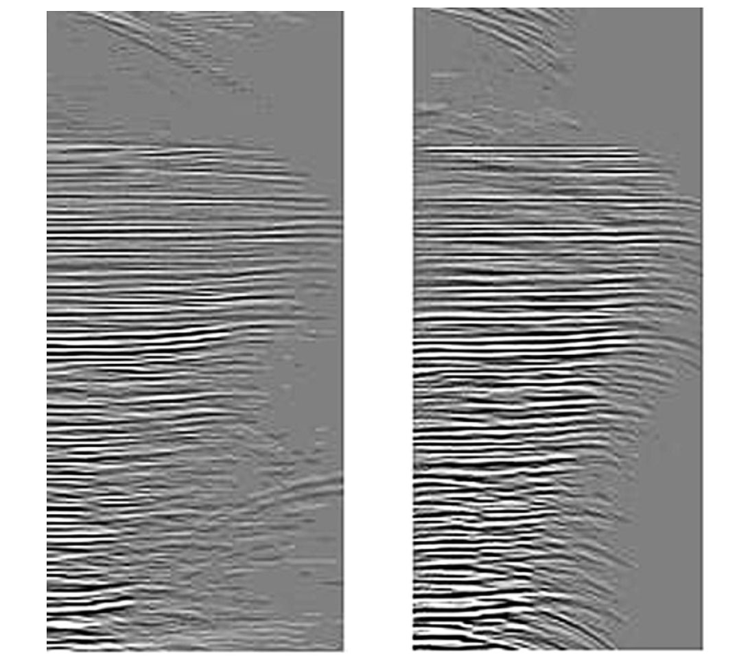
Reverse time migration can produce image gathers on a regular grid that could be input to subsalt velocity update. If the imaging condition of shot-profile reverse time migration is modified to output CIP Gathers (see Figs. 4a & 4b), these can be analyzed for velocity determination in any velocity model building step.
After finalizing the velocity model through the sub-salt velocity update and then modeling, if necessary to explain the questionable events, the final migration is executed.
Conclusions and future work
Reverse time migration, with the advantage of turning ray, multi-arrival capabilities and no approximations on amplitude control, can provide us with an algorithm that can be used to build consistent velocity models and perform final pre-stack depth migration. Achieving a more accurate salt geometry and sub-salt velocity model can be key to a successful image. In terms of runtime, the method is feasible if the new marine long offset and large cable number is considered. Reverse time migration is an excellent modeling tool which can aid us in understanding and/or validating imaging doubts during the model building procedure. Furthermore, this method’s modeling capability can be used to carry out the essential input to the waveform tomography that will revolutionize the velocity model building process.

Related Reading


Join the Conversation
Interested in starting, or contributing to a conversation about an article or issue of the RECORDER? Join our CSEG LinkedIn Group.
Share This Article