Abstract
Increases in ground falls over the last few years have prompted the Saskatchewan potash industry into researching new ways to increase mine safety and awareness. Ground conditions in a potash mine are very dynamic and the back stability changes continually due to the pseudo elastic nature of the ore. Also, due to the immense size of the potash mines, any practical ground analysis system needs to be versatile as well as portable. Ground Penetrating Radar (GPR) is the technology having the highest potential for success as a detection system. Early GPR test programs in potash suggested that GPR could produce images of the back conditions, potentially highlighting propagating cracks and clay seams. Follow up testing was slow but further illustrated the technologies positive detection potential. Frequency and operations testing proved that a 200 MHz antenna mounted on an underground vehicle travelling over 10 kph, achieved penetration and interpretation depths of over 10 metres. The proven GPR system technology can now be extended and adapted onto mobile equipment to act as an early warning system for immediately deteriorating back conditions.
Résumé
Les augmentations dans les chutes de sol ont incité durant ces peu de dernières années l’industrie de potasse de Saskatchewan dans préparer les nouvelles façons pour augmenter la sûreté de mine et la conscience. Lesl conditions au sol dans une mine de potasse sont très dynamique et les changements de stabilité arrières continuellement en raison du pseudo la nature élastique du minerai. Aussi, en raison de la taille immense des mines de potasse, les besoins de système d’analyse de sol pratiques d’être variés de même que portatifs. Fonder Pénétrant le Radar (GPR) est la technologie ayant le plus haut potentiel pour le succès comme un système de détection. Le test premier de GPR programme dans la potasse suggérée que GPR produise des images des conditions arrières, soulignant potentiellement de fissure propageant et les coutures d’argile. Donner suite à l’essai était lent mais plus ample a illustré les technologies le potentiel de détection positif. La fréquence et les opérations essayant ont prouvé qu’une 200 antenne de MHz montée sur un véhicule souterrain voyage par-dessus 10 kph, la pénétration atteints et les profondeurs d’interprétation de par-dessus 10 mètres. La technologie prouvée de système de GPR peut être étendue maintenant et peut être adaptée sur l’équipement mobile pour servir d’un système d’avertissement premier pour se détériorant tout de suite de retour des conditions.
Introduction
The Mosaic Potash Colonsay (Colonsay) and Mosaic Potash Esterhazy (Esterhazy) minesites are located approximately 76 and 450 kilometres east of Saskatoon (Saskatchewan), respectively. Production started at the Esterhazy operations in 1962 and Colonsay in 1969. Both operations use continuous mining machines to extract the ore at average extraction ratios ranging from 35% at Colonsay to 50% at Esterhazy. Ground control and stabilization in a potash mine, or in any mine, is crucial to the safety of the mine, but more importantly, critical to the safety of all its employees. Each of the Saskatchewan companies have been involved in their own internal research into ground condition assessment, however, in 2002, the Saskatchewan Potash Producers Association (SPPA) formally embarked on a collaborative initiative to improve the diagnostics involved in ascertaining the stability of the mine opening, and in particular the roof (back) by establishing a Loose Detection Committee. Mine operators have historically relied on their vision or hearing to determine the quality of the ground in the back. Visible cracks can be seen, and audible hollow sounds can be heard when striking the back with a scaling bar. These methods are subjective, and are certainly reactive. A more proactive approach was sought, and a means to determine the quality of the back was required that was simple, accurate, and fast. A literature search of potential geophysical tools was conducted, and the use of a Ground Penetrating Radar (GPR) system emerged as the system with the highest probability of success. Previous work by Annan et al, and each of the Saskatchewan potash companies further substantiated the assessment. Single and Multi-frequency radar tests were conducted with Mosaic Potash (formerly IMC Potash) taking the lead in the Single frequency approach. Mosaic Potash contracted Golder Associates to conduct several tests with numerous single frequency radar systems including Sensors & Software and GSSI. The IDS system from Italy was also tested. All the systems produced better than expected radar results in the potash and salt beds; however, for the purposes of Mosaic Potash, the IDS system proved most versatile as it was easily adaptable for fast acquisition using an underground vehicle. Between the Esterhazy and the Colonsay underground operations are over 1600 km of open travelways, and over 20 active working headings that require monitoring. Additionally, various antenna frequencies were also testing for diagnostic analysis of the Esterhazy Water Inflow area to determine if zones of weakness, loss of potash continuity, or water flow paths could be detected deeper in the back.
Historical Ground Monitoring
Over the last 40 years of potash mining, mine operations have relied extensively on the diagnostic skills of ground control personnel to establish whether or not an area of ground is safe for access. Methods have included visual and audible checks, and occasionally, with drill hole confirmations. Visual checks involve an operator driving throughout the mine workings while focusing a high powered rayed light onto the back, and looking for any signs of ground failure. Visible flaking or small tension cracks can often lead to more serious ground conditions. Establishing the severity of the ground condition, thereby, dictates what level of maintenance, support or rehabilitation is necessary. After an area of active heading has been mined, the area is “sounded” for ground stability. This involves an operator striking the back with the tip of a scaling bar and listening for the corresponding sound or echo. The quality of the sound can indicate the condition of the ground. A high pitched “tink” indicates a more solid back, whereas a lower pitched “thunk” indicates there is a separation within the back. This type of diagnostics relies heavily on the ear of the worker, and obviously, can be very subjective. Knowing how high up the “looseness” is will also be important in remedial plans. A horizontal separation less than a metre above the back is much more critical than a separation 2 or 3 metres above the back. In order to effectively complete the visual or audible diagnostics, a small diameter hole is often drilled to establish the parameters of the crack or sound identified. Separations are identified in the hole using a tape measure or a video borehole scope. The tape measure is quick to use, but is less informative. Essentially, a worker raises the end of the tape up to the top of the hole, and then slowly pulls the tape out. The end of the tape will catch on cracks and separations, and these locations are recorded. The borehole scope provides a visual reference of the hole, and is used when a more horizontal view is required. The scope is able to display a view looking into the separation. This becomes a slow and tedious solution to ground control identification and establishment of correct controls. Ultimately, numerous rockbolts are installed prior to establishment of actual ground conditions in order to secure the ground “just in case”. Many rockbolts are installed into ground where ground support is not required and can actually be detrimental to the overall stability of the surrounding mine openings.
Geology
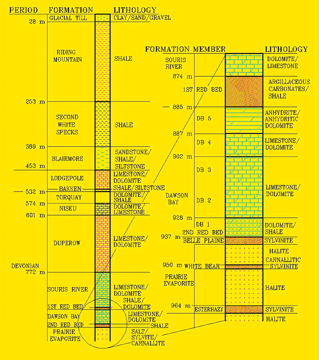
Typical composition of the Esterhazy ore (Esterhazy Potash member) is 55% halite, 40% sylvite, 4% carnallite and 1% insolubles (clays). The Colonsay ore (Patience Lake Potash member) is characterized by a higher insoluble content and absence of carnallite. The ore zones are Middle Devonian in age and located within the upper Prairie Evaporite Formation at an average depth of 961 metres (Esterhazy) and 1020 metres (Colonsay). The Prairie Evaporites are disconformably underlain by highly permeable dolomites of the Winnipegosis Formation and unconformably overlain by shale and water bearing carbonate strata of the Dawson Bay Formation (Figure 1). On average, 13 m (Colonsay) to 30 m (Esterhazy) of salt provide an impermeable barrier between the Dawson Bay Formation and the mine horizon. Approximately 430 metres of Devonian and Mississippian carbonates (with some shale) overlie the Dawson Bay formation followed by 450 metres of Cretaceous sandstone/ shale and glacial sediments.
Potash has a unique material characteristic which allows the rock under certain stress conditions to deform and flow in a time dependent manner. The degree of deformation observed underground is dependent on several factors: panel extraction, mineralogy of the ore zone (clay seams, ore grade), room and pillar design, age and geometry of opening.
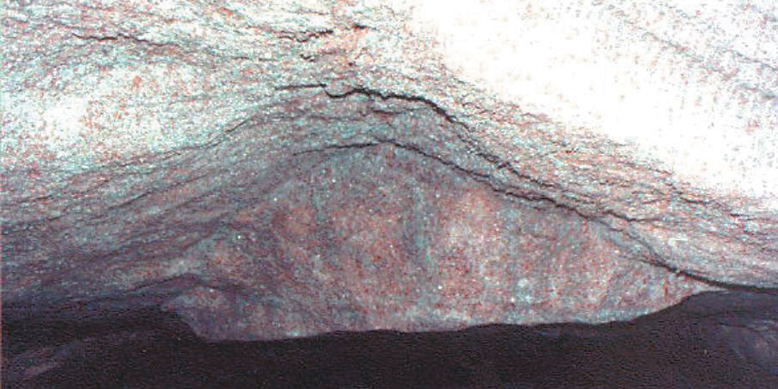
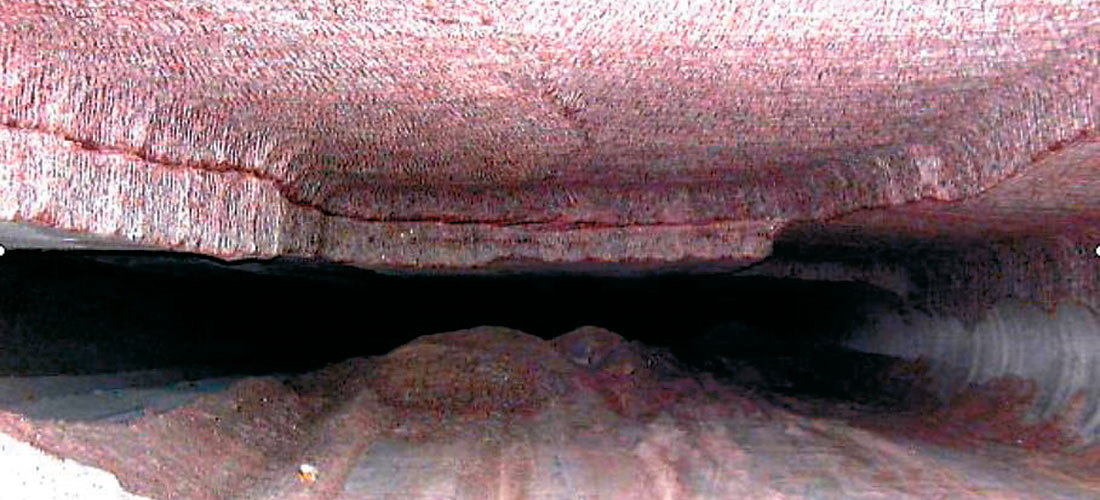
Two types of separation that are commonly observed in a potash mine are shown in Figures 2 and 3. Development of the first type (stress arch) will first appear as shear cracks along the far edge of the roof. Visual observations by mine personnel will often detect these cracks early enough to design and implement a ground support program to prevent a potential ground fall. The second type of separation occurs along geological contacts such as clay seams and bedding planes.
Research Ideology
Several incidences of roof falls and ground related injuries prompted the Saskatchewan Mines Branch to ask what industry was doing to reduce the ground related risks. The SPPA responded with a collaborative initiative and instillation of the Loose Detection Committee. This reinforced the proactive direction the potash companies have maintained in their approach to the changing and challenging potash ground conditions. Several consulting firms were contacted to submit proposals to the SPPA concerning what tools or technologies were commercially available which would assist in the assessment of ground conditions above an underground opening in a proactive manner. Primary consideration criteria required the technology be able to map the clay horizon in the roof accurately (Saskatoon area mines), the equipment be suitable for use in underground potash mines, and the systems or technologies be capable of being installed and operated continuously on existing equipment in a safe, practical and reliable manner. Initial choices of potential tools included GPR, Resistivity, Electromagnetic, and Natural Gamma measurement methods. Based on the contrast in physical properties between potash, clay, water, and air (Table 1), and the 2001 preliminary investigations, GPR emerged as the most likely technology for success.
The propagation of a GPR signal depends mainly on the electrical properties of the subsurface materials. The transmitting antenna radiates a short high-frequency EM pulse into the ground, where it is refracted, diffracted and reflected primarily as it encounters changes in dielectric permittivity and electrical conductivity. Waves that are scattered back toward the earth’s surface induce a signal in the receiving antenna, and are recorded as digitized signals for analysis (Basson 2000). Both single frequency and multi-frequency (step frequency) GPR systems were possible solutions, with Mosaic Potash leading the single frequency approach, and Potash Corporation of Saskatchewan (PCS) leading the step-frequency approach on behalf of the SPPA.
Selection criteria
The GPR system must be able to provide information on a continuous basis which indicates clay and crack locations within threshold distances of the back, not interfere with normal mining practices, be commercially available to simplify and expedite part replacements, be autonomous, and ultimately require very little operator input. The unit or system needs to be used in three different and distinct situations; old accessible travelways, new cutting faces, and proactively on the cutting miner. It is understood that the same system and equipment may not be applicable for all three situations. Also, while not a primary selection criterion, the vast extents of the potash mine workings dictates that the selected detection system needs to be installed on a vehicle in order to adequately monitor the back throughout the mines. Initial requirements are focused at vehicle usage which entails mounting the equipment and system on an underground vehicle in order to traverse active mine workings to assess the current ground conditions. Boom mounting of the scanning GPR is required to get the antenna close to the back. This is more of a requirement in the Colonsay operation where typical floor to back height ranges from 3.3 – 4 metres. Typical floor to back height at the Esterhazy operations is 2.4 – 2.7 metres. The primary response the GPR will provide is the location of cracks and separations in the back. Esterhazy’s back is essentially clay free, and any cracks should be identifiable. As noted previously, the Colonsay potash zones are often differentiated by clay seams. The mining face is designed to cut out the #1 seam. Failure to cut out this seam will result in loosening of a thin zone which will very quickly fail, and fall. Above this layer is 0.7 – 1 metre of salt followed by another clay seam. Geotechnical studies have indicated that a minimum 0.6 metre of salt beam is required in order to maintain a competent back (in areas of “normal” ground conditions). A GPR unit on the mining machine can detect this seam and evaluations can therefore be made on its integrity and on the salt thickness from the back to the clay seam. With the GPR on the mining machine, immediate assessment of salt beam thickness can be made, and necessary remedial plans can be made to secure the ground. Esterhazy does not have the associated clay seam close to the mined ore zones, and therefore do not need the advanced diagnostics. Lastly, a system is required for local assessments. After initial soundings, a more informative survey may be required. This would entail a hand held system that is portable, and can be easily used by face foremen, or ground control operators. Many times an assessment is required at or near the working face which would not be reachable from the vehicle system. The portable system would be used in these circumstances to assess back conditions, and to be used to assist the operator to make reasonable assessments, and recommendations for primary ground support requirements.
A vast amount of ground needs to be covered in a potash mine, so the speed of information acquisition is critical to producing a timely study of an area. In initial GPR equipment testing, both point, and continuous modes of acquisition were tested while varying parameters such as gain, stacking, acquisition speed and spacing. Point acquisition mode involved recording multiple recordings at a single point (stacking tests), and continuous acquisition mode involved investigating how the results responded when the antenna was moved along the wall or back. On surface, this aspect is easier as a continuous contact with the medium can be achieved. Underground, special equipment needed to be constructed in order to hold the antenna to the back. Alternatively, for short tests, the antenna was held onto the back and wall by hand.
Depth of penetration desired differs between Esterhazy and Colonsay. In Esterhazy, cracking of the back will often start from the wall sides and propagate towards the middle and over the mine entry. Total depth of the crack is a direct function of entry width. In Colonsay, the clay seams in the back tend to dictate the cracking, and more often than not, the cracks tend to occur in tension in the middle or the entry. As such, typical desired depth of radar penetration for Esterhazy is 2 – 3 metres, while in Colonsay it is 1 – 2 metres. Depth of penetration in the Esterhazy Water area is required over 10 metres in order to delineate an upper marker bed (White Bear Marker).
System Development Progression and Frequency Testing
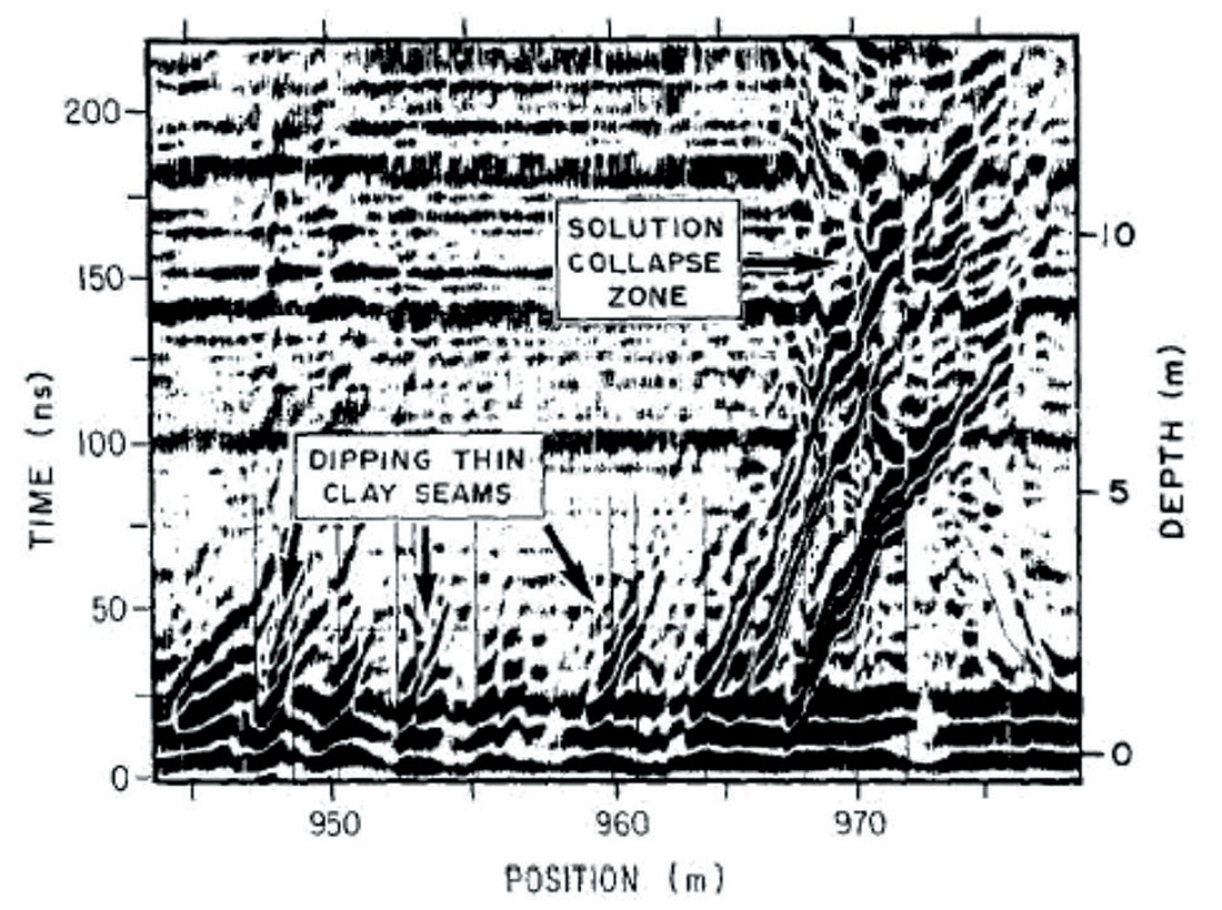
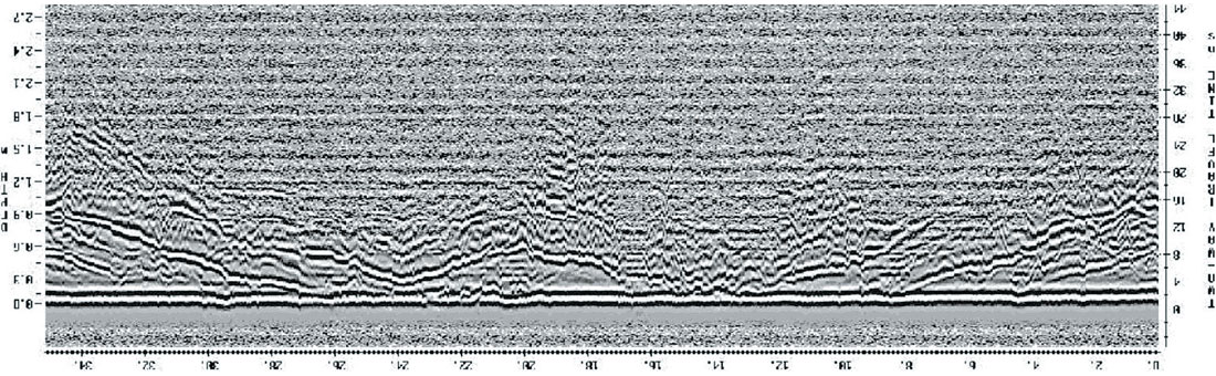
Radar experiments in Saskatchewan potash dating back to 1988 showed that radar is an effective method for probing salt/potash environments (Annan et al). However, at that time, a lack of availability of a comprehensive system prohibited its use in this mining environment. However, as shown below (Figure 4), the results of the radar were encouraging.
In 2001, SPPA companies coordinated a preliminary study into radar acquisition using Sensors and Software’s 500 MHz Noggin system. The radar unit was mounted on a fibreglass boom attached to the back of an underground vehicle to avoid suspected interference problems associated with the vehicle’s steel construction. This was confirmed when a mobile equipment passed the test vehicle, and an interference pattern could clearly be identified. A heavy duty spring arrangement provided a force to hold the antenna onto the back while the truck was being moved. Resultant data was informative in that it again illustrated the positive possibilities of radar in potash. Future data acquisition and processing improvements were still required in order to make an employable unit at that time.
In 2002, a more concerted approach to loose detection was taken, and several consulting firms were contacted for proposals to determine a viable means of assessing the ground conditions above an opening in potash mines. GPR was recognized as the tool with the most promising success possibilities. Golders initial testing utilized Sensors and Software, and GSSI equipment and software. Both point and continuous testing was performed and data sets compared. Figure 5 illustrates a raw data response, and clearly indicated that GPR could be very effective in mapping out features in the Saskatchewan potash mine environment.
Various antenna frequencies were also testing in searching for an optimum frequency for acquisition knowing that the primary depth of interest was from 0 to 3 metres. Frequency testing included 200, 400, 500, 900, and 1500 MHz involving multiple passes over the same area, and then a comparison of results post processing. Acquisition involved holding the antenna directly onto the back, and in point mode, acquiring a new point incrementally, and in continuous mode, acquiring points continuously while maintaining antenna contact with the back while the jeep was moving. Both methods resulted in slow acquisition.
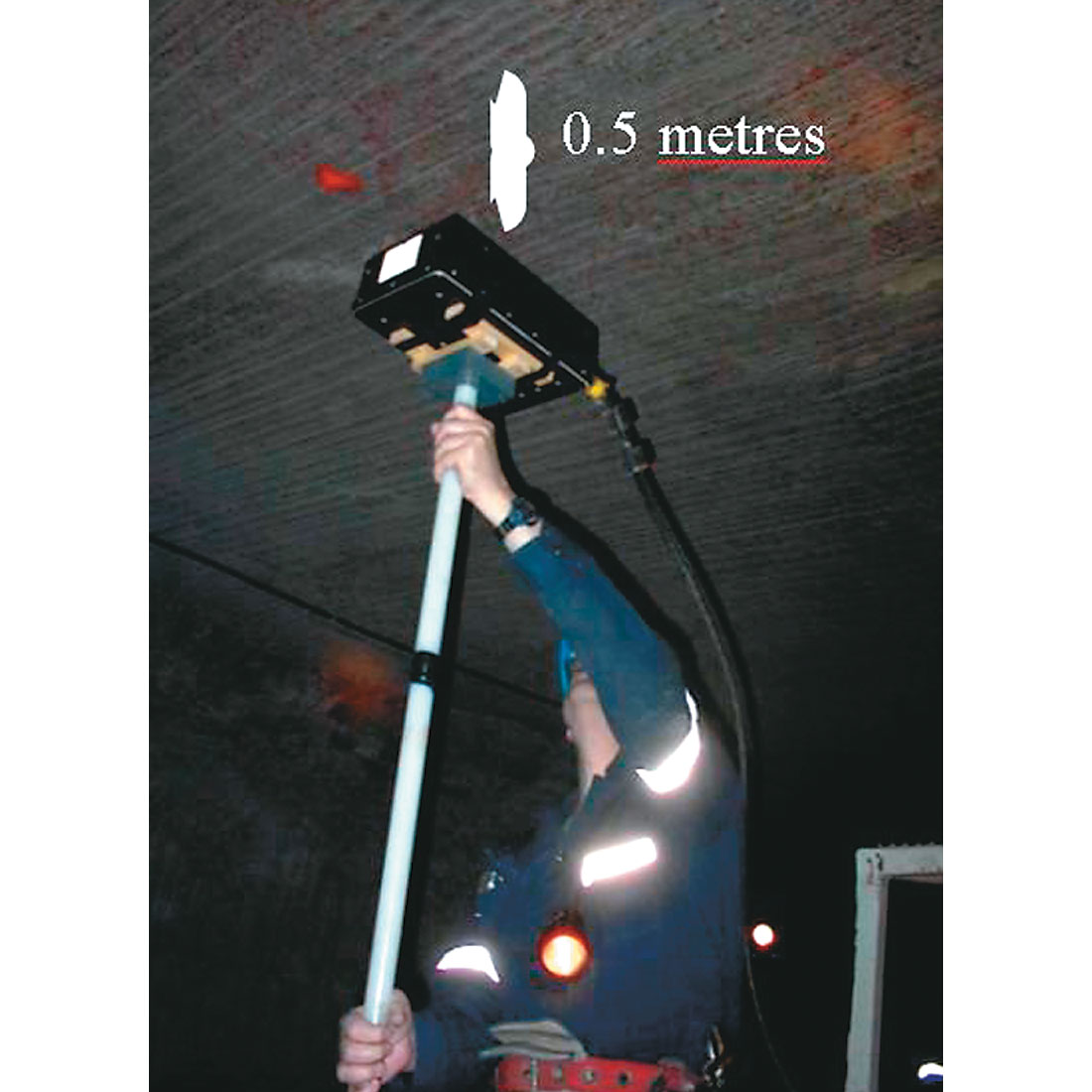
In early 2003, correspondence with Kali und Salz (K+S), confirmed that K+S had been successfully employing GPR for ground condition assessments for several years. Dr. Alan Coode (IMC/Mosaic) and Dr. Volker Lukas (K+S) collaborated and arranged for K+S personnel to bring the system they used into the Saskatchewan Potash mines for testing. K+S were using the acquisition system developed by the Italian company Ingegneria Dei Sistemi (IDS), in conjunction with an older generation GSSI 900 MHZ antenna. Subsequent testing in both Esterhazy and Colonsay proved that a system could be successfully used without having an antenna directly on the back (Figure 6) thereby allowing for potentially faster acquisition speeds.
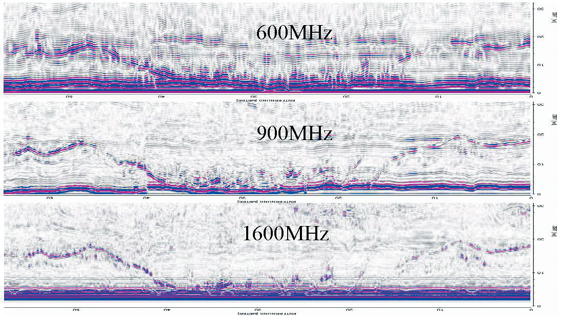
Not having to have the antenna in contact with the back provided the possibility to complete mine wide surveys in a reasonable amount of time. Further frequency testing indicated that a frequency of around 900 MHz was good for detection of cracks and clay seams (Figure 7). Ultimately, a 950 MHz antenna was developed for and purchased for both the Esterhazy and Colonsay operations.
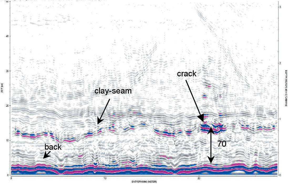
In the Saskatoon area, the mines are producing ore from the Patience Lake potash member which contains numerous clay seams. From a ground control standpoint, the clay seam approximately 1 metre above the back is the most important. The beam between the back and the clay seam is usually competent if it is at least 0.6 metres thick. Less and the back will tend to loosen and could fall. By mapping this distance, the mine operators can make an assessment on the potential future back conditions. Many cracks also occur along the clay seam. When employing the GPR, distinguishing between the intact clay seam, and a separation or crack in the clay seam is essential in ground assessment. Figure 8 is an example of what the GPR produces from a clay seam and crack. Attenuation of signal was encountered with the first clay seam (1 metre deep), which resulted in poorer imaging of clay seams deeper into the back. However, this first seam is the most important for immediate back condition assessment.
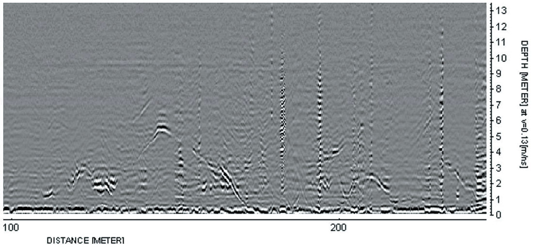
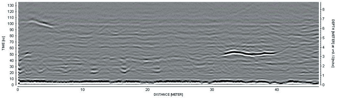
With the success of back condition assessment using the GPR in the production areas, additional frequency testing was undertaken to see if GPR could effectively be used in the Esterhazy water inflow area to assess conditions deeper into the back. Subsequent testing indicated that by using a 200 MHz antenna, features as deep as 10 + metres could successfully be delineated. Figure 9 shows some significant features, lower cracks, and the White Bear marker (10 metre). Figure 10 illustrates potential water filled cracks or zone 7 and 3 metres into the back.
Acquisition and Implementation
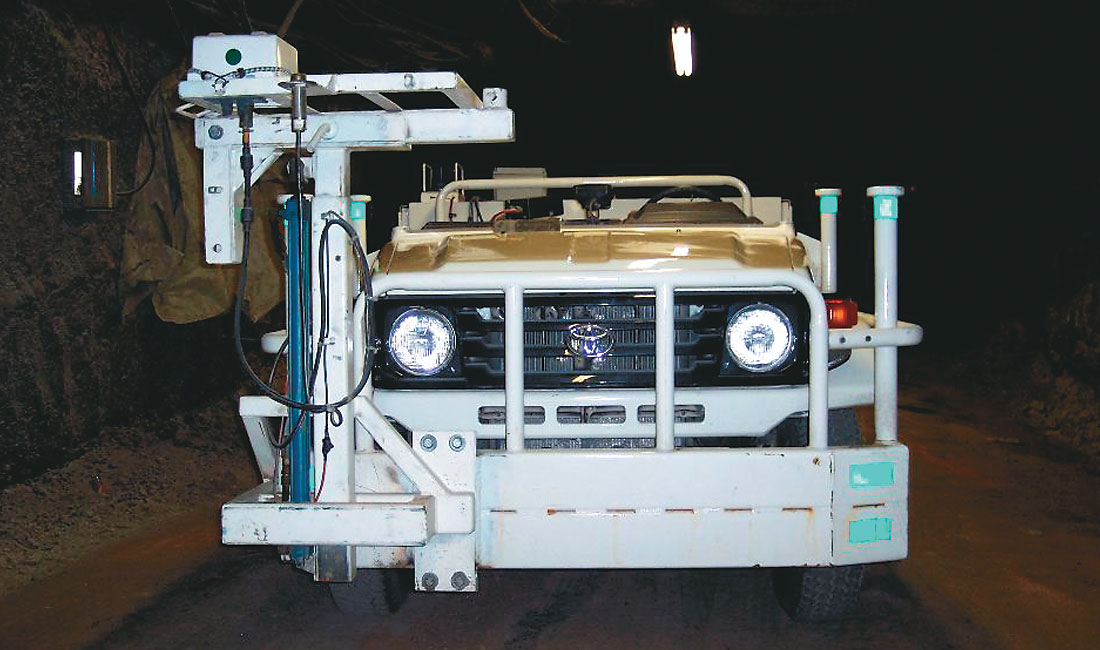
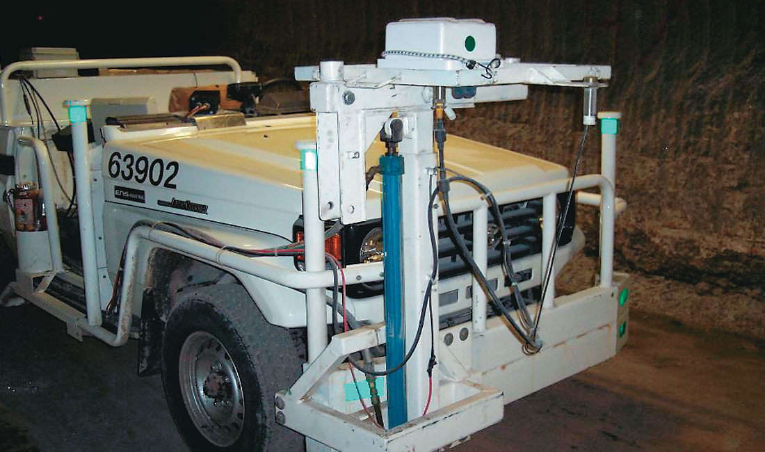
With the amalgamation of a modified underground vehicle (Toyota Landcruiser) and the ground penetrating radar system, the Esterhazy mine developed a mobile radar unit that makes wide scale data acquisition relatively easy and possible for one operator (Figure 11).
The Field Acquisition System is comprised of two main components, an Antenna Control Unit (ACU) and a Data Logger unit (DL) (Figure 12).
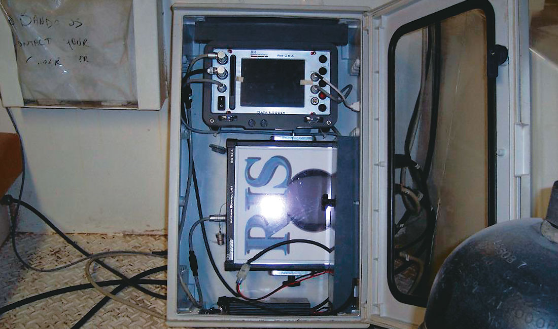
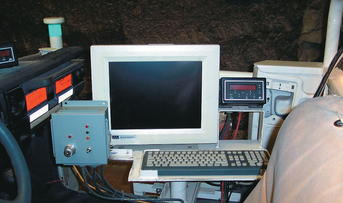
The ACU controls the functions of sending and receiving signals as well as providing power to all connected antennae. Though the application involves the use of only one antenna for data collection, the ACU is capable of controlling as many as four antennae through piloted sequence acquisitions. The DL unit is essentially a scaled down version of a typical personal computer. With a Pentium MMX 266 MHz processor and 6 GB hard disk, the DL includes a 6.4 inch, touch screen sensitive, SVGA display. The acquisition system is situated in the back of the vehicle, and is connected to a 15 inch external monitor and keyboard sitting in the passenger seat area. This is used by the driver for controlling the Windows 98 operated computer (Figure 13).
Coordination between the ACU and DL is appropriated by the GRASWin3 software code which is activated by the user prior to the start of a survey.
The vehicle is fashioned with a radar antenna platform connected to a single stage hydraulic lift that can be controlled by the operator and used to adjust the antenna to address variations in back height (Figure 14). Though presently operated manually, the antenna adjustment process has the capability of becoming automated. On board meters provide a distance traveled as well as a height measurement from the antenna platform to the back. With the turn of a key on the control box, the computer, onboard meters, and hydraulic system are started. The radar vehicle utilizes an isolated two battery system, with each battery handling a portion of the electrical load. One battery powers the truck and hydraulic pump while the other services the needs of the computer, monitor, and meters. Both are simultaneously charged by a single brawny alternator while the vehicle runs. (Figure 14)
For the purpose of mine workings assessment, the 950 MHz, monostatic antenna is being used. The frequency of this antenna was determined to provide the best resolution and ability for crack detection while reaching a penetrating depth of over 3 metres in Esterhazy. A 200 MHz antenna is also available for use and can achieve penetration depths of over 10 metres, albeit, due to the lower frequency, has lower detail or resolution.
Upon activation of the GrasWin software, the user can access menus which allow for the control of various parameters such as radar configuration and display settings. As part the pre-survey routine, an antenna signal test and calculation of an automatic gain factor are performed. Once completed, the operator has the opportunity to enter a custom, user-defined gain curve if so desired. Data collection is continuous and begins with movement of the vehicle once the start of the survey is initiated. Collection pauses with a stop in vehicle motion and ends with the termination of the survey. Acquisition speeds in excess of 10 KPH are possible without any significant loss of data quality. Survey distance is measured by both the computer itself (via wheel mounted pulse transducer) as well as the onboard meter for comparison. The radar section produced is displayed on the monitor located to the right of the operator.
Radar surveys at the Esterhazy operation are conducted along the length of an excavation in 1000 metre sections. The survey line is spaced approximately 2.4 metres from the wall and conducted on both sides of an entry to assure proper coverage. During the survey, points of interest can be recorded with the software and marked with a dotted line for later recognition. Once completed, and after the acquisition software has saved the file, data can be transferred via USB flash drive for further processing elsewhere. REFLEXW, a processing software package, is used to further filter and analyze the data collected. Both the raw data file and final processing file are saved on a local area network folder stamped with both the location and date of the survey. In the event that something of concern is observed, further investigation is taken. If deemed a possible risk, a report is issued that outlines the area of concern, as well as a plan to address it.
Future opportunities
Future opportunities and natural progression is towards the hand held, and miner mounted systems. Each has its particular importance to ground safety. Other SPPA members have actively pursued and installed successful miner mounted systems which are primarily used to detect the clay seam in the back, and to give the miner operator warning if the salt beam thins. Hand held systems are currently being investigated.
Although loose detection remains as the primary focus for ground penetrating radar at all the Mosaic Potash operations, additional applications for future use are being considered. One such application is the measurement of salt back thickness. Using a low frequency antenna, GPR may be used to determine the thickness of the evaporite sequences that exist above the present mine workings. This data is useful as an additional tool in assessing conditions that might pose concern at a later date or at least a need for monitoring (i.e. an unusually thin salt back).
From a production standpoint, the opportunity to use radar for locating marker beds is a promising possibility. At the Esterhazy mine, a rather competent seam of anhydrite can be consistently found at approximately 6 metres below the mine workings. In a scenario where abnormal geology is encountered, this procedure could be used to help locate the anhydrite layer therefore providing a guide to help navigate miners through the area.
Summary and Conclusions
Ground Penetrating Radar has clearly illustrated that it has an important role to play in improving the general safety in a potash mine; directly influencing ground condition assessment, and remediation. Testing has shown that effective crack identification can be seen using a 950 MHz antenna, and that crack and clay differentiation is also possible at 950 MHz if the crack is large enough, or several close cracks. It was noted that the clay seams at the Colonsay mine attenuate the radar signal, which results in poorer imaging deeper than the first clay seam. Mounting a radar unit on a vehicle for large surveys is also possible by employing an antenna that does not maintain contact with the back. Although some depth imaging is lost, enough penetration energy remains to produce an adequately comprehensive image of the back deep that is good enough to make quality ground condition assessments. Usage of a lower frequency 200 MHz antenna has provided for imaging of greater than 10 meters into the back. Deep enough to assist in qualitative analysis of back structure in the Esterhazy Water Inflow area. Success has resulted in three systems now obtained by Mosaic Potash for use in its potash operations.

Acknowledgements
The writers would like to acknowledge the contribution of a number of people and contributors to the paper.


Join the Conversation
Interested in starting, or contributing to a conversation about an article or issue of the RECORDER? Join our CSEG LinkedIn Group.
Share This Article