For some time I’ve wanted to investigate automatic transmissions – I think it’s my inner German gearhead calling. In my lifetime automatic transmissions have evolved from sloppy, lurch-prone systems to the ultra-sophisticated transmissions like the 8-speed one in my truck. I’ll start with conventional mechanical clutch-operated transmissions, and then take it from there.
Manual Transmissions And Gear Basics
Regarding the physics of gears, who needs a trip down memory lane to high school physics? Not me, life is too short. Gears allow the operator to adjust the tradeoff between speed and torque appropriately, let’s leave it at that. I always think of bike gears because I can see them and I’m the engine, so I understand exactly what is going on: the bigger the front gear, the faster the back wheel turns and the lower the torque (and vice versa); the bigger the back gear, the higher the torque and the lower the speed (and vice versa). So gears allow an engine’s power, which is essentially limited to a narrow range, to deliver high speed and low torque to the driving wheels, say for instance when cruising along a flat highway, all the way to low speed and high torque, such as when towing a trailer up a hill. This tradeoff is determined by the ratio of the input to output gear sizes, where gear size is expressed by number of teeth:
SI/SO = TO/TI (S is speed, T is number of teeth, subscripts indicate input (I) and output (O))
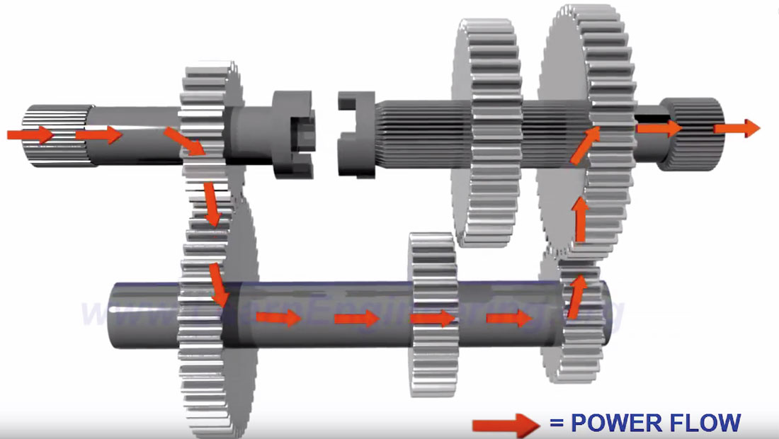
Before I go any further, I’d like to recommend the many great YouTube videos that show how transmissions work. They illustrate so well what I will inadequately try to describe in words and pictures (but please read on!) Figure 1 shows a simple 3-speed manual transmission. On the left is the input shaft which comes out of the engine. On the right is the output shaft that drives the car’s wheels. Connecting the two is a counter shaft. As pictured, the transmission is in 1st gear: the input gear is small and the output gear large, so we have the high torque necessary to get the car moving. The shift to second (and this brings back memories of an old Holden in Australia and wrestling with its “3 in a tree” gear shift on the steering column) would slide the output gears to the left, disengaging the right one, and engaging the left one. Third gear is achieved by disconnecting the counter shaft entirely, and directly connecting the input and output shafts.
In practice, this primitive system involved a lot of metal-onmetal grinding. Drivers had to learn how to intuitively pay attention to the sound of the engine and the speed of the car, so as to let the clutch out at the exact moment when the speeds of the input and output gears were very close, thus allowing them to mesh with no grinding. To eliminate this issue, constant mesh transmissions were developed. With this system, the gears on the output shaft are always engaged with their counterparts on the counter shaft. The secret is that only one output shaft gear is actually locked to the output shaft at any time – the rest just spin freely at whatever speed is dictated by the counter shaft. Figure 2 shows the main components involved in locking the desired gear to the output shaft, which is where the true beauty of the system lies.
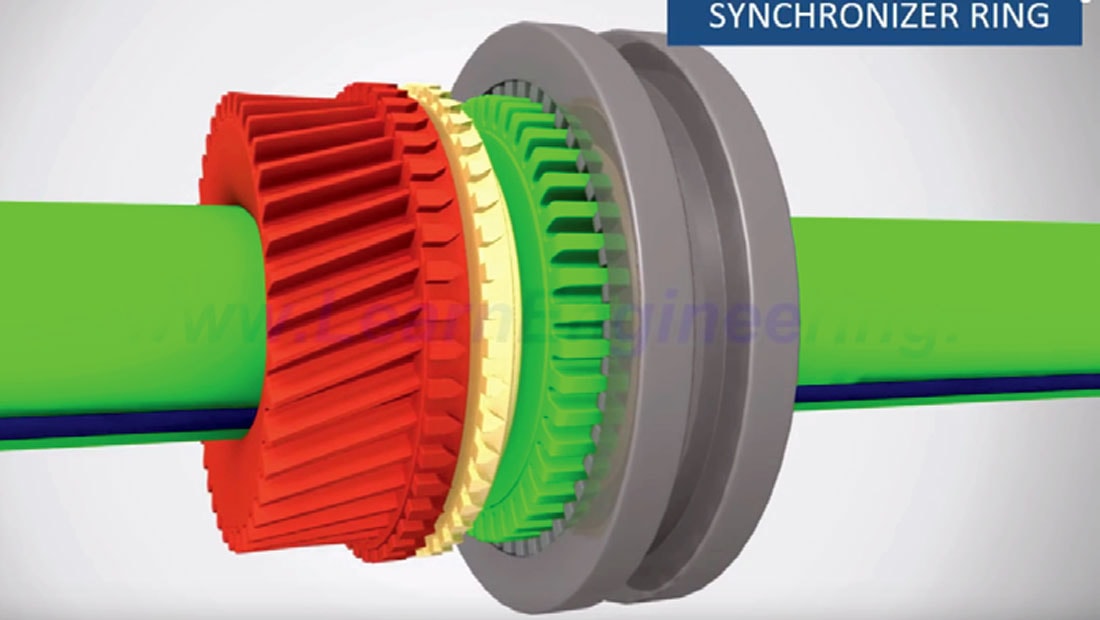
The red gear on the left is the one which our hypothetical driver will shift to, meaning it will go from spinning freely on the output shaft to being locked to the output shaft, and driven by the gear on the counter shaft. The green gear hub on the right is always locked to the shaft. When the driver engages the clutch, power from the engine to the drive shaft is disconnected. When she shifts the gear lever, the previous gear is disconnected (basically the reverse of what I will describe here), and the grey connector sleeve slides to the left, and engages with the freely spinning yellow synchronizer ring. As the connector sleeve pushes the synchronizer ring further to the left, friction between the yellow ring and red gear cause the red gear to start spinning at the same speed as the yellow ring, and hence green hub. The grey sleeve continues to slide to the left and onto the narrow teeth on the right side of the red gear, thus locking the red gear and green hub with no grinding. The driver then releases the clutch, and power is delivered from the input shaft, through the counter shaft, to the output shaft and on to the drive wheels. That is all you need to know about manual transmission basics to understand the more complex automatic transmission systems described below.
Hydraulic Automatic Transmission
The first automatic transmission was invented in 1921 by Alfred Horner Munro of Regina (yay Canada 150!), but it used compressed air. The first automatic transmission to use fluid coupling was patented in Brazil in 1932 by José Braz Araripe and Fernando Lehly Lemos, who sold it to General Motors, which further refined it and introduced it commercially in the 1940 Oldsmobile Hydra-Matic transmission. I should note that there is some evidence that a fluid coupling automatic transmission was developed around the time of WWI in Germany at a Ferdinand von Zeppelin company called ZF Friedrichshafen (ZF stands for Zahnradfabrik, meaning the company name is literally Frederick’s Harbour Gear Factory) for use in their zeppelins. Regardless, a greatly improved version of these early examples is essentially the system found in most cars today. The evolution of automatic transmissions with its many variations is fascinating, but I’ll skip all that; if interested, check out Wikipedia (Wikimedia Foundation, Inc., 2017a).
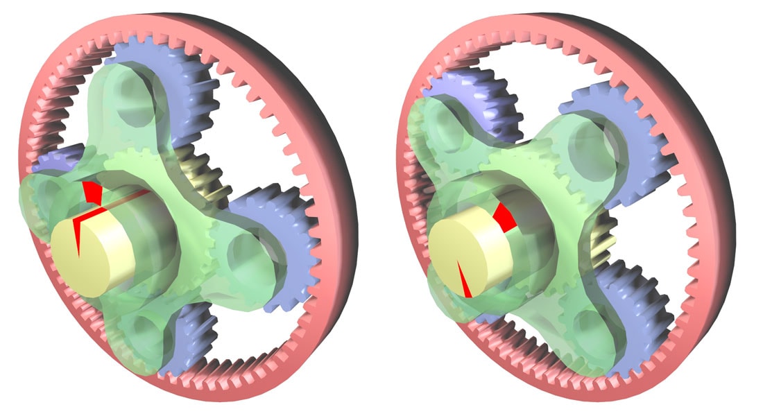
In a hydraulic automatic transmission, a fluid coupling system is used in place of a mechanical clutch, and instead of the simple gears shown in Figures 1 and 2, planetary gears are usually employed. I find planetary gears fascinating, and maybe they possess some kind of universal appeal that explains the popularity of Fidget Spinners. The reason that they are called planetary gears is that they sort of resemble a planetary system – see Figure 3. This actually reminds me of a previous Science Break article (Kuhn, 2012) on the Antikythera device, an ancient machine that used planetary gears to predict the positions of the known (then) planets in our solar system. In Figure 3, if the carrier (green) is rotated 45° clockwise then the planet gears (blue) turn within the fixed ring gear (pink), thus rotating the sun gear (yellow) and its shaft almost 180° clockwise. The same gear ratio rules hold here, although they are more complicated to figure out. However, it is easy to see that if the big ring gear was rotated with the carrier fixed, then the small sun gear would rotate more than 3 times faster, similar to having your bike chain set on the big gear at the pedals, and small gear at the rear wheel. But I’ll get into planetary gears in more detail later.
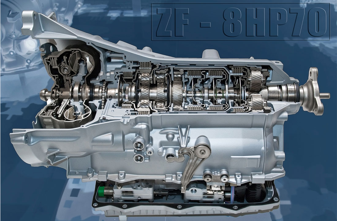
Figure 4 is a cutaway graphic of the 8-speed ZF 8HP hydraulic automatic transmission found in all recent BMW’s with automatic transmissions and, coincidentally, the transmission in my Ram Eco-Diesel truck. If you guessed that the ZF in the name indicates this modern transmission is made by the same Zeppelin company mentioned earlier, you are correct! The next two sections delve into the torque converter seen on the left (engine input) side of Figure 4, and the planetary gears, making up most of the rest of the right side of the transmission in Figure 4. Note that the bottom of the transmission houses the hydraulics and other components that control the systems that actually move the various gears and clutches.
Torque Converter
The torque converter is a key component in a hydraulic automatic transmission, as it replaces the mechanical clutch in a manual system. The key challenges it overcomes in the absence of a human to connect and disconnect engine power are to: (1) not stall when the vehicle is slowed down to a halt, and (2) provide additional torque during initial acceleration from a standstill.
Most of the explanations on the Internet of how a torque converter actually works are very confusing or incorrect, so I’ll devote more space to this and try to do better. A simple analogy to help understand how a torque converter can deliver power to the rear wheels when the car is moving, and not transfer any (or very, very little) power when the car is stopped, with no intervention required, is this: picture two fans facing each other, one with a motor, and the other spinning freely. If the motor is turned on, the first fan blows air on the second one, which will spin, with spin direction dictated by the angle of its blades. If a brake is applied to the free spinning fan it will stop, but the first (motorized) fan will continue to spin. Keeping that simple analogy in mind, now refer to Figure 5, which shows the basic components making up a torque converter.
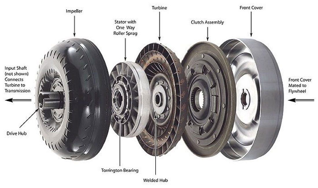
On the right side, which is where the engine sits, is the front cover. It is directly bolted to the engine flex plate (so called because it can flex with the changes in shape of the torque converter due to internal hydraulic pressures), which is connected to the engine’s crankshaft. So connected, the cover spins at the exact same rpm rate as the engine. The cover mates directly to the impeller or pump at the rear, and those two enclose all the other components plus the transmission fluid. Because it is directly connected to the cover, the impeller obviously also spins at the same rate as the engine. With the cover and impeller fixed to each other, the torque converter is essentially a toroid or donut shaped system full of transmission fluid that is always spinning, and it sits inside the fat bell housing at the front of the transmission. Directly opposite from the impeller is the turbine; it can spin freely, and is connected to the output shaft. Note that both the impeller and turbine are bladed – they are like propellers or fans, with blade characteristics optimized for interaction with transmission fluid.
Let’s say the car is stopped at a red light, and the engine is idling. At this low rpm level, the impeller spins and churns the transmission fluid a bit, but with the brakes applied, nothing happens – it’s like our hypothetical motorized fan, with the speed set on low and we’re holding the other fan still with our fingers. The very little torque generated by the fluid hitting the turbine blades is not enough to overcome the force of the brakes holding the car still.
When the light turns green and the driver gives the engine more gas, the impeller spins faster (dark green arrow) and acts like a centrifuge. The transmission fluid inside its bowl shape is forced outwards and channeled along longitudinal blades towards the turbine at the front of the unit (blue arrow). This moving fluid hits the outer blades of the turbine, which then starts to spin (lime green arrow). The turbine is connected to a shaft which passes through the middle of the impeller and out to the transmission. The turbine and impeller are like mirror images of each other, and you can picture the transmission fluid exiting the outer edges of the spinning impeller, hitting the outer blades of the turbine, entering the turbine, shooting back out the centre of the turbine to be sucked back into the impeller in a closed cell of circular fluid movement throughout the donut shape. It all sounds very exciting, but it is not very good at getting a motionless turbine moving – fluid coupling is effective when the impeller and turbine are moving at close to the same speed, but it is increasingly ineffective as the difference in speed is greater. What is needed is a way to trade off speed for torque, something discussed earlier with mechanical gears, but here we need to achieve it within a fluid coupling system. This is where the stator, which sits in between the impeller and turbine, comes in – it creates a variable reduction gear effect.
The stator also has blades or vanes, a smaller diameter than the impeller and turbine, and can only rotate in the same direction as the impeller. Under initial acceleration, the transmission fluid is forced out from the blades on the edges of the impeller (blue arrow), going directly to the blades of the turbine, turning the turbine. The fluid continues into the centre of the turbine where it is ejected outwards towards the stator in a somewhat turbulent flow (red arrow); in fact, its direction is mainly counter to the rotation of the impeller. The one way gear holds the stator static, and the fluid is forced through its vanes, slows down and exits at close to a 90° angle in such a way that it now hits the impeller’s inner blades in a complementary way, thus actually assisting the impeller’s rotation (orange arrow). As the turbine moves faster and faster, the stator starts to rotate, the feedback effect lessens, and the whole system – components, fluid and all – rotates close to synchronously, and maximum fluid coupling is approached.
The net effect of this dynamic feedback mechanism is that at lower turbine speeds the impeller’s speed is converted to more torque by up to a factor of between 2 to 3; as the turbine comes up to speed this torque multiplier effect is reduced, until at about 50-60 km/h in most cars maximum efficiency fluid coupling is achieved, something called the stall point. Now the last main component kicks in: the lock-up clutch brings the impeller and turbine together, achieving mechanical coupling for maximum efficiency.
Planetary Gears
I’m afraid that after the drama of the torque converter, the planetary gears might seem rather ho hum in comparison. But trust me, they are exciting as well! Let’s refer back to the planetary gear in Figure 3. Several different gear ratios can be achieved with a single planetary gear – it all depends which gear is fixed, and which of the other two is the driver, and which is the driven. The table below shows three possible gear ratio outputs with a ring gear of 72 teeth, and a sun gear of 30.
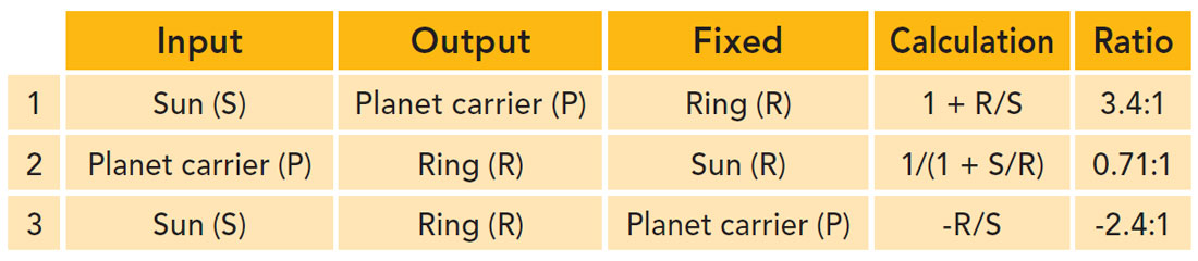
Set up 1) is a reduction gear, with input speed being 3.4 times faster than output, but proportionally higher torque – this is a typical first gear ratio in a car. Set up 2) is the opposite, with output speed being faster than input – a ratio of 07:1 is a typical 5th or 6th gear in a car. Set up 3 is a typical reverse reduction gear ratio. Note if any two of the gears are locked, then a 1:1 ratio is achieved, which is what 4th gear in a car usually is.
Many automatic transmissions contain compound planetary gears with two sun gears – one large, one small – and two sets of planetary gears, all within one ring (Figure 6). These systems can get fiendishly complicated. Referring back to Figure 4, it looks like there are 3 regular planetary gears in the ZF 8HP transmission, with the 4th on the right side being a compound one, but I may be mistaken.
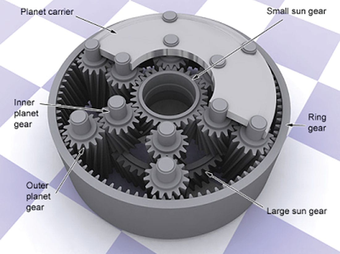
Let’s use Figure 6 to show how four typical forward gears can be achieved with a single compound planetary gear. We will assume that the ring gear has 72 teeth, the large sun 36, and the small sun 30.
For 1st gear, if the small sun is rotated by the shaft connected to the turbine in the torque converter, and the planetary carrier is held stationary by a one-way clutch, then we have the same situation as 3) in the table above – a ratio of -2.4:1; however, because there are two planet gears, the sign is reversed back to positive, and we’ve got 1st gear.
2nd gear is achieved via two stages. In the first stage the small sun is the input, the large sun (36 teeth) acts as an intermediate ring gear, and the output is the planet carrier. The gear ratio is given by 1 + R/S = 1 + 36/30 = 2.2:1 ; the second stage is made up of the planet carrier as the input driving the second planetary gear set, the large sun is of course still stationary, and the output is the true ring gear. This second stage gear ratio is given by 1 / (1 + S/R) = 1 / (1 + 36/72) = 0.67:1 Gear ratios in a multi-stage gear system are multiplicative, so 2.2 x 0.67 gives a second gear ratio of 1.47:1.
3rd gear here is a bit simpler but interesting: both sun gears are locked to the turbine shaft. With both sun gears turning in the same direction, the planet gears lockup, because they can only move if they are turning in opposite directions; this in turn locks the ring to the planets, and the entire system rotates at the same speed as the turbine – a 1:1 gear ratio.
Finally, 4th is more accurately called overdrive. A clutch connects the torque converter cover/impeller directly to the planet carrier, i.e. the torque converter and turbine are entirely bypassed. The two sun gears are held fixed by what is called the overdrive band, and the ring gear is the output. The gear ratio for this is given by 1 / (1 + S/R) = 1 / (1 + 36/72) = 0.67:1.
If you’ve ever wondered how gears inside bike or scooter wheel hubs work, now you know – they stick a single compound planetary gear in there.
Semi-Automatic Transmissions
I had hoped to really get into this modern type of transmission, but I’m already up over 3,000 words, a bit too self-indulgent even by my standards. Briefly, these are transmissions that have been around for quite a while, but they really came into their own with the availability and integration of computers in car engines. These modern semi-automatics first showed up in high end sports cars like Porsches, and are now somewhat commonplace. They are actually mechanical clutch transmissions, but the clutch-shift-declutch process is done automatically by complex systems involving sensors, computers, hydraulics, pneumatics, actuators and so on. These transmissions typically do not use planetary gears, rather their gears usually use conventional input, output and counter shafts like the ones in Figure 1.
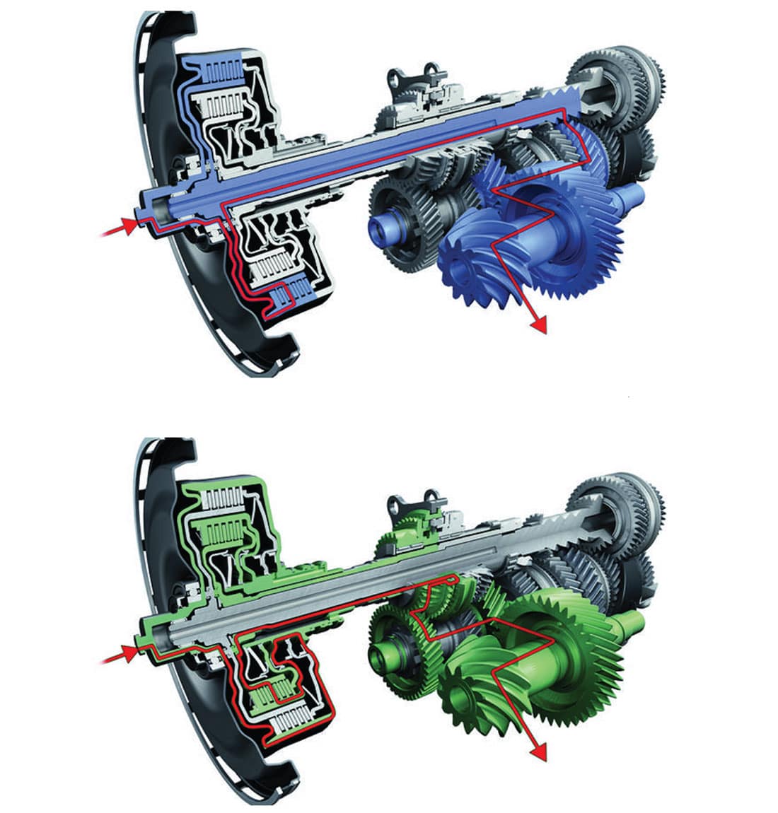
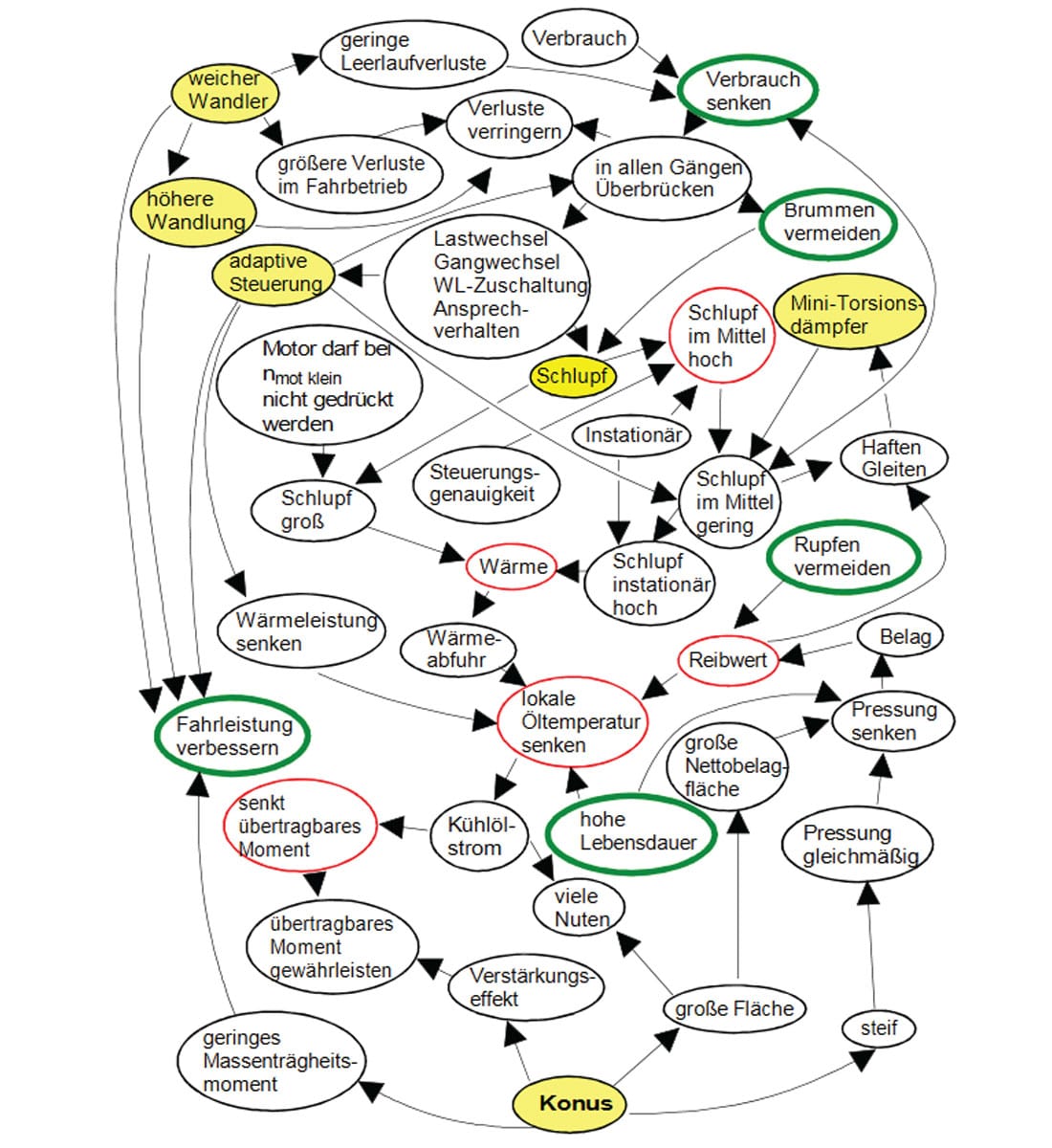
Semi-automatic transmissions are amenable to manual override, and this is what paddle shifters and similar are. Porsche’s PDK (an acronym that includes the gorgeous German compound noun, Doppelkupplungsgetriebe, or double clutch system in English) is a good example (Figure 7). One clutch is linked to the odd-numbered gears, the other to the evens. This means that as one gear is mechanically disengaging, the next gear, higher or lower as the case may be, is engaging, in a lightning fast and smooth operation. These are typically sequential transmissions, meaning they can’t skip gears and select at random as with a manual shift – they can only go up or down to the next gear over. Speaking of Germans, their crazy nouns and love of diabolically complicated engineering, I want to share Figure 8 with you, which is a bubble diagram of all the interrelated effects at play within a particular automatic transmission.
Continuously Variable Transmission (CVT)
The last type of modern automatic transmission I’ll touch on is high tech, but decidedly mundane, at least from a driver experience perspective. For a while I had a Camry Hybrid with a CVT in it, and that thing was the epitome of bland. But interesting in its own right. CVT’s are not particularly efficient – about 88% meaning that 12% of power is lost to heat and so on – but they deliver several important advantages. Because they offer an infinite range of gear ratios between upper and lower limits, the exact gear ratio can be selected at any given speed to deliver either the maximum efficiency or maximum power. They are also lighter and simpler meaning they are cheaper to produce and fix, and they are suitable for small, lower power engines such as in snowmobiles, ATV’s, golf carts and scooters.
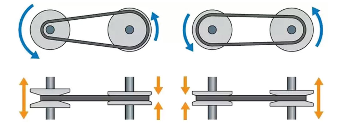
The most common type of CVT is called a variable-diameter pulley (VDP). As seen in Figure 9, there is an input drive shaft parallel to an output driven shaft. Each shaft holds two cone shapes which together create a v-shaped pulley, and the two pulleys are connected by a v-shaped belt or chain that fits snuggly into the conical pulleys. On each shaft the cones can move further apart or closer together. Typically if one set of cones moves together, the other two simultaneously move apart. The net effect of this is that the diameter of the first pulley gets smaller, and the diameter of the second gets larger – changing the gear ratio but the required length of the belt stays the same.
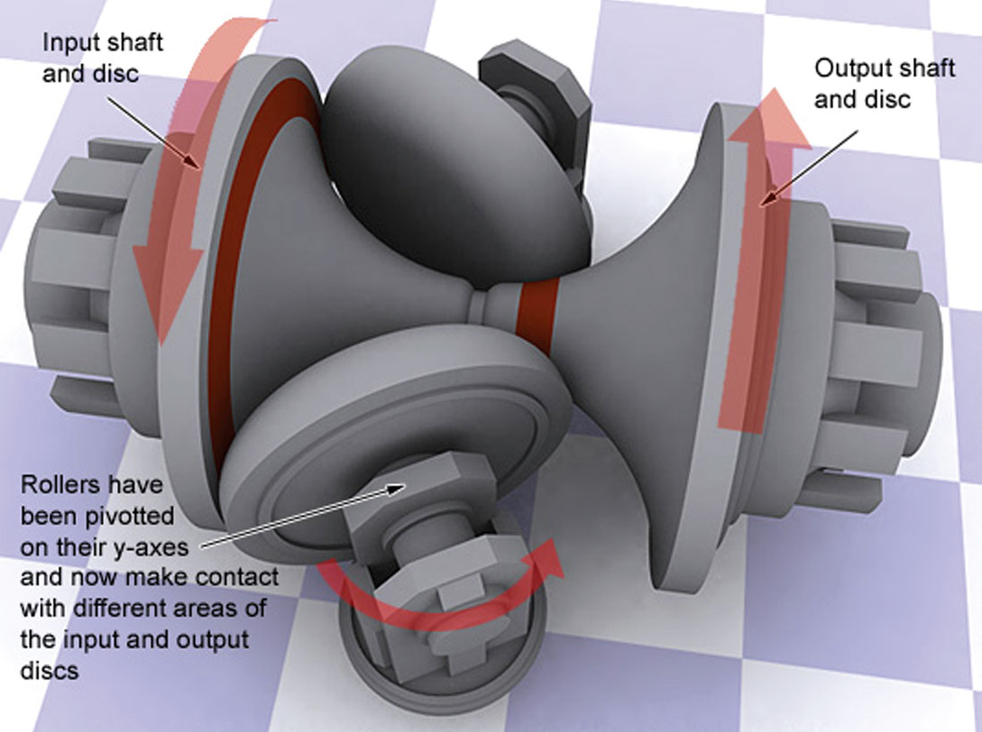
There are actually numerous ways to achieve a CVT. For example, Figure 10 shows a toroidal CVT. Instead of a belt or chain, the input and output gears are connected by a pair of rollers. As pictured, the effective diameter of the input gear is large, and the output’s is small – this would deliver high speed/low torque to the output shaft. By rotating the rollers to the right, this progressively lowers the effective diameter of the input gear and the opposite for the output. This changes the gear ratio continuously towards lower output speed and higher torque. There are several other viable CVT systems, each interesting in their own right.
To finish up, I discovered that the transmission in my “Blandmobile”, aka the Toyota Camry Hybrid, is a very interesting type of CVT. Toyota uses a couple of acronyms to name this technology: e-CVT with the ‘e’ standing for electronic, or HSD (Hybrid Synergy Drive); other manufacturers have their own brands. In fact, most hybrids that advertise a CVT transmission actually use a single standard planetary gear. The trick is that the planetary gear is used to “blend” the gas and electric power to create a CVT, basically by allowing all three gears to move at the same time, instead of the usual practice of holding one stationary. To do this, there are two electric motors in addition to the internal combustion engine (ICE); each motor is connected to one of the three main gear sets. In the Toyota example I describe below, the generator doubles as the second motor.
Please refer to Figure 3 again. In Toyota hybrids and others, the electric motor (M2) delivers power to the outer ring gear, and is connected directly to the differential driving the wheels – this means the speed of the wheels is the same as that of the electric motor M2. The generator (M1) is connected to the sun gear, and the internal combustion engine (ICE) to the planet carrier. Here are the stages the system can go through:
- From 0 kph to about 40 kph the power is entirely from M2 drawing on the battery. Because the ICE is off, the planet carrier is stationary, and the planets are forced to spin. They in turn spin the sun gear and M1; M1 is allowed to spin freely. The gear ratios dictate that for every turn of M2, M1 does about 2.6 rotations, so M1 is soon spinning quite fast.
- At about 40 kph M1 has reached its maximum spin rate, which is about 6500 RPM. At that point the computer tells the system to apply an EM field to M1 by sending power to its coil from the battery. This has the effect of slowing M1, which forces the planet carrier to turn and start the gas engine. At this point all three motors are driving their respective gears, but it is still M2 that drives the wheels.
- When the vehicle is up over 40 kph, the ICE runs, but at no time is it directly connected to M2. If M2 and the ICE are turning at the same speed then M1 turns at the same speed also, and does not act as a generator, and M2 drives the car purely from battery power. If the ICE is turning faster than M2 then M1 acts as a generator, and the extra power delivered to the battery can be used to assist M2. The computer responds to the signal from the accelerator pedal and senses how much assist is required to achieve the desired speed. In this way power is delivered smoothly to the wheels only through M2’s electric power. Note that electric engines have flat torque curves – they deliver maximum torque from just above 0 RPM all the way to their maximum rotation, so that speed/torque tradeoff is really not an issue. All M2 needs to spin faster is more power as the gear ratios in the planetary gear have been chosen to comfortably deliver from 0 kph up to the vehicle’s maximum.
- If the battery needs charging at any time, the ICE is available to charge it up, whether the vehicle is moving or not.
- For reverse gear, M1 is used as a conventional engine and draws power from the battery, and it spins in the opposite direction as M2.


Share This Column